¶ Assembling mecha figure application placement
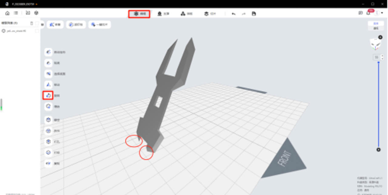
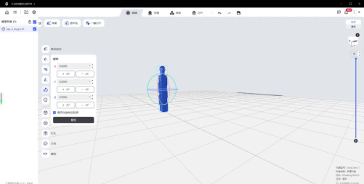
At the top of the software interface, click on the "Edit" area "Select Bottom" + "Pan" + "Rotate" function, and place the model to be printed according to certain principles ( Based on the principles of feature surface facing up, acute angle facing up, cup mouth facing down, and less support ), the step-by-step operation is as follows:
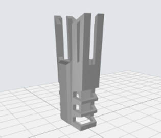
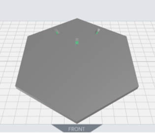
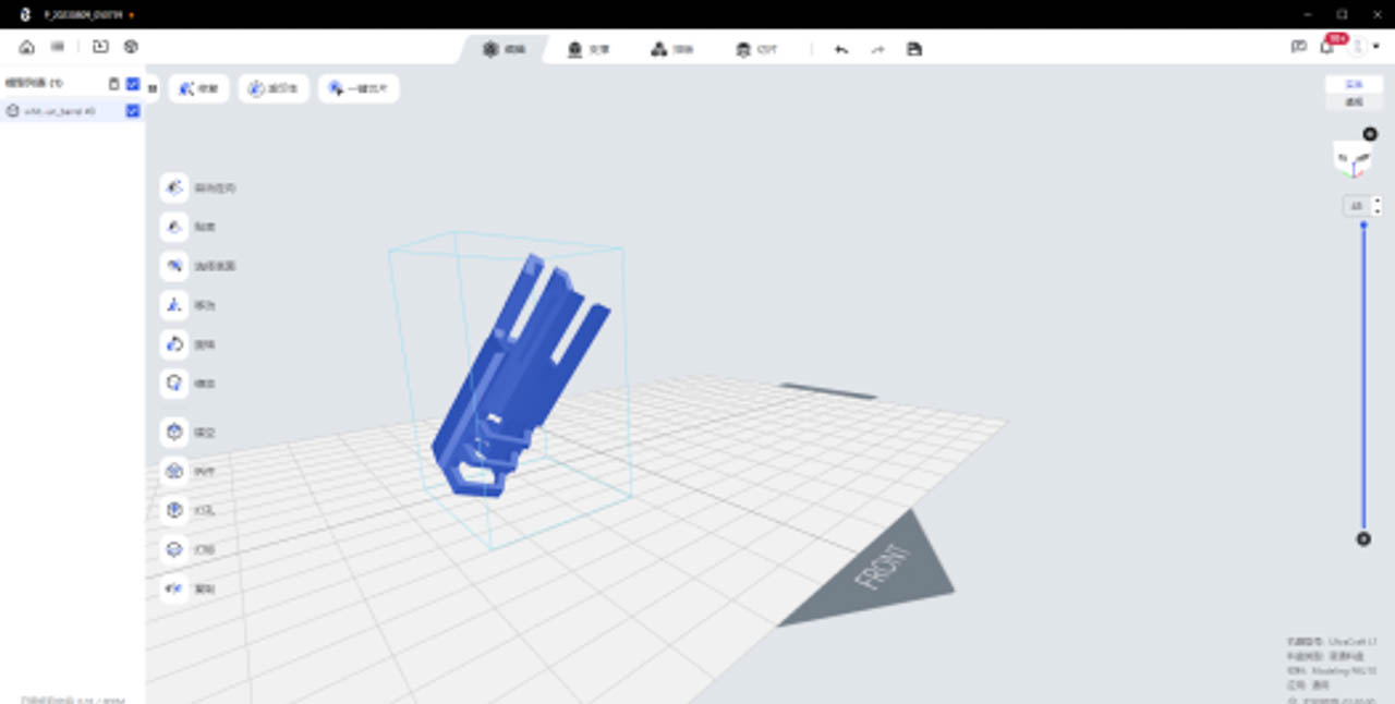
General principle : In order to ensure the surface quality of the detailed texture parts, the flatness of the lower surface of the beam, the success rate of solid long pole or large plane printing, it is necessary to place the feature surface facing up, the structure with the beam tilted (60 ° with the platform) placed, solid long pole or large plane tilted (30-45 ° with the platform) placed;
 |
 |
 |
 |
 |
 |
When placing the model, avoid the plane or straight edge parallel to the printing platform to reduce the printing area of each layer as much as possible, which can effectively reduce the peeling force generated when printing the model and ensure the printing effect.
Generally speaking, the important details of the model need to be placed facing up, because the added support will affect the surface details of the model. After removing the support, polish it as needed.
| Helmet texture structure | Barrel with beam | Waist with beam | Solid long rod | Large plane |
 |
 |
 |
 |
 |
 |
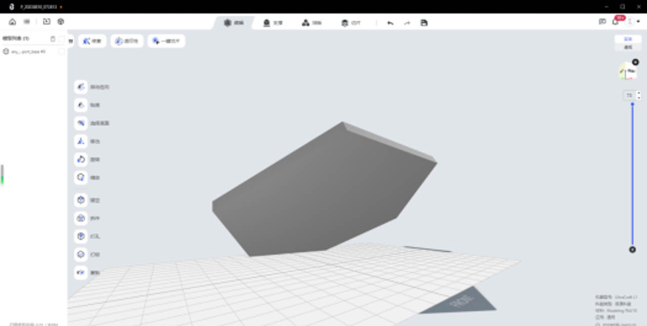 |
| Example of placing a multi-beam model tilted 60 ° | a large plane model tilted 45 ° |
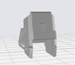
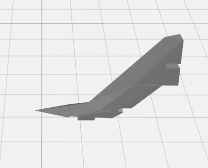
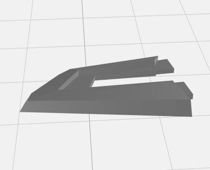
Mecha acute angle structure , in order to ensure the sharpness of the acute angle, the acute angle structure needs to be placed upward (otherwise the acute angle will be blunt or print defect).
| Shroud with acute angle | Acute-angled tail wing | Skirt with sharp angles |
 |
 |
 |
 |
 |
| Example of placing high-sharpness structures facing up | high-sharpness structures facing up |
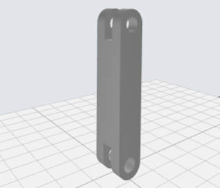
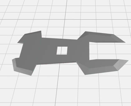
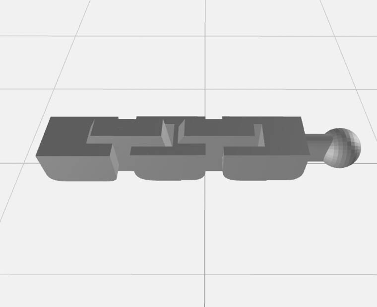
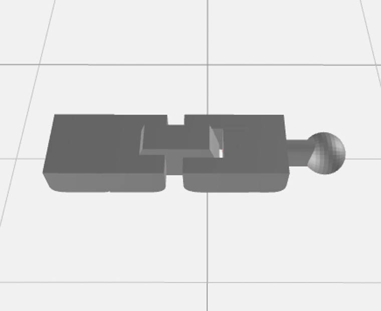
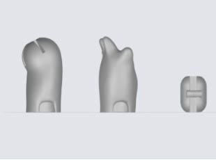
Mecha integrated activity structure , in order to ensure the normal function of the integrated activity structure, the structure needs to be placed horizontally (because the gap is small, stacked and printed, easy to stick).
| Fingers with integrated movable structure | The thumb of the integrated movable structure |
 |
 |
 |
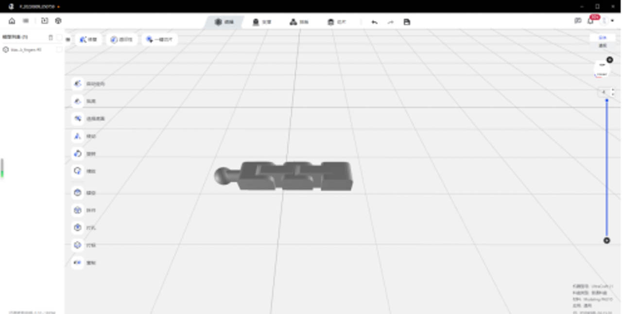 |
| Example of the effect of placing the active structure gap upward | the active structure gap upward |
¶ Miniature application placement:
Use the "Move" function to adjust the placement of the model, and the "Rotate" function to adjust the angle of the model. Refer to the different placement methods of the miniature application as follows.
| Serial number | Model classification | Placement instructions | Placement indication |
| 1 | Face and fine feature texture structure | Place it facing up to avoid adding support to the face and fine feature texture structure | 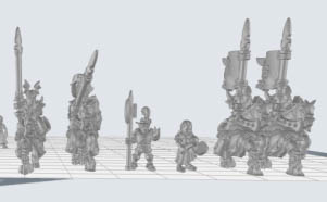 |
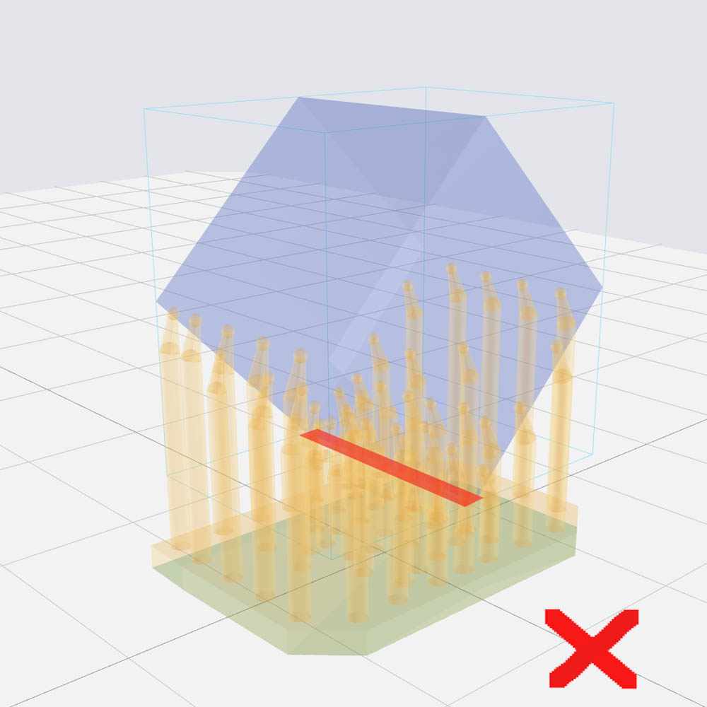
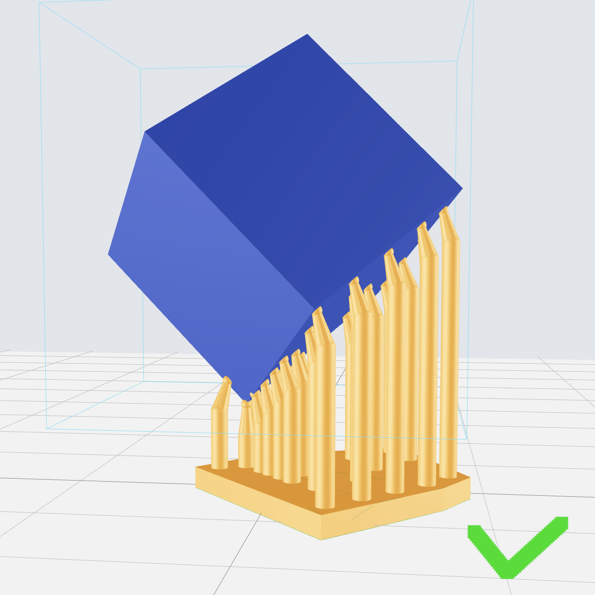
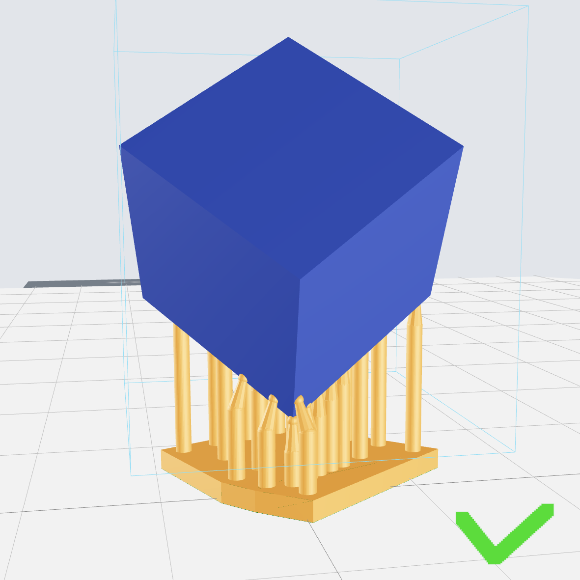
| 2 | Platform type large plane structure | 1. The base is slightly tilted to avoid a large section 2. When the surface requirements are relatively high, the recommended tilt angle is 41.09 °, and the corresponding support angle is recommended to be 45 °; When the surface requirements are low, the recommended tilt angle is 30 °, and the corresponding support angle is recommended to be 35 °. |
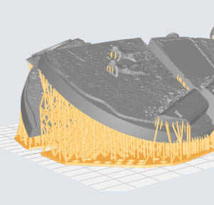 |
| 3 | Scale models (military models) | This type of structure includes large planar structures and feature structures. It is recommended to tilt and place them. When the surface requirements are low, the recommended tilt angle is 30 °, and the corresponding support angle is recommended to be 35 °. | 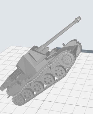 |
| 4 | Other models | No specific placement method, based on the principle of pouring cup mouth and less support | 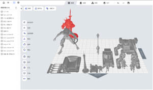 |
¶ BJD Figure Application Placement
Use the "Move" function to adjust the placement of the model, and the "Rotate" function to adjust the angle of the model. BJD applies different model placement methods as follows.
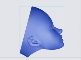
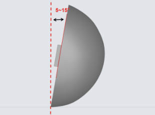
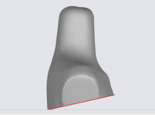
| Head - front face | Head - posterior skull | Thoracic platform | Other models |
| Tilt the face upwards, with the neck facing the platform, avoiding support on the face | Slightly tilt back (about 5 °~ 15 °) to avoid generating support on the assembly plane | Place the neck up and tilt the base slightly to avoid large sections | No specific placement method, based on the principle of pouring cup mouth and less support |
 |
 |
 |
 |
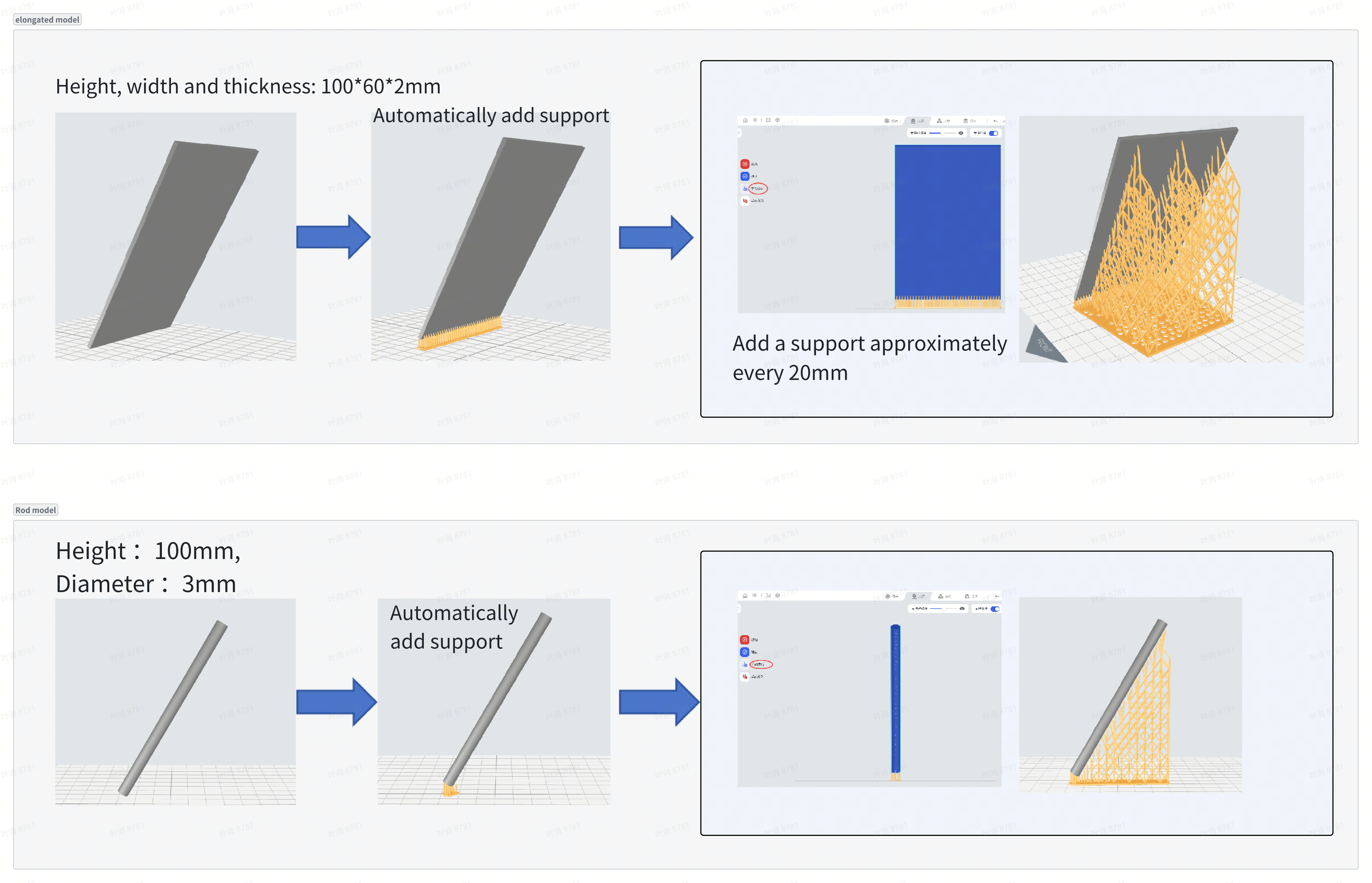
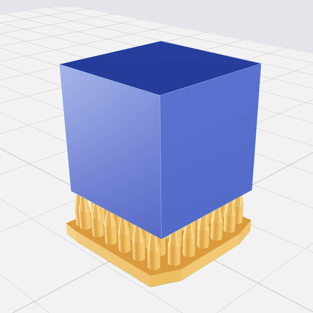
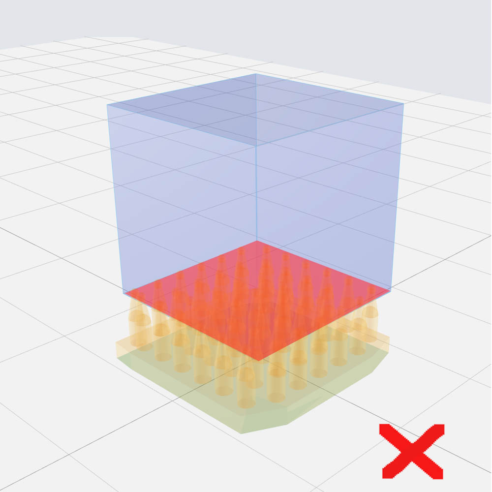
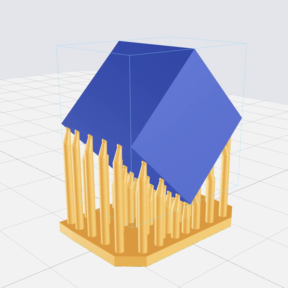
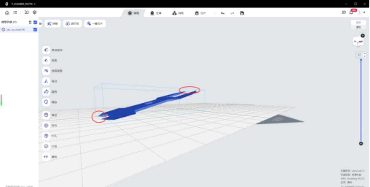
¶ Off-center-of-gravity model placement
Background and purpose: When a model deviates from the center of gravity, such as a rod-shaped or elongated model placed vertically (with a tilt angle greater than the unsupported angle), there is no support below the tilt direction of the model, causing the center of gravity to shift, which may ultimately lead to printing deformation, staggered layers and other adverse effects. At this time, it is necessary to manually add support to ensure the success of printing.