¶ Design Principles
¶ Shape Requirements
Avoid sharp edges (very acute corners on print parts) or abrupt transitions between perpendicular sides (where two surfaces meet at a 90-degree angle). These features are susceptible to cracking and separation during printing due to stress concentration, and finishing processes such as sanding and polishing become more challenging. Additionally, the difficulty in achieving a flat surface during sanding can lead to varying degrees of depressions, which in turn result in inconsistent light refraction during spraying/polishing, ultimately affecting the final appearance. Instead, it is recommended to design rounded or chamfered edges, to ensure a uniform change in shape.
Minimize abrupt changes in cross-sections (sharp changes in the cross-sectional dimensions and shapes over a short distance with no transitions). Such changes can create uneven stress during printing, leading to lines that cannot be corrected in subsequent processes. Instead, it is advisable that changes in the part's shape occur gradually and linearly.
¶ Consistent Wall Thickness
The print part’s wall thickness should be as consistent as possible. Inconsistent thickness will lead to inconsistent light refraction, resulting in ripples or cloudy areas that cannot be remedied later, and also cause the print part to contract unevenly during curing, leading to warping and other defects.
¶ Hollowing
Solid parts will lead to significantly more bubbles generated inside. Reasonable shelling can reduce the bubbles to ensure transparency while also decreasing printing time and resin consumption.
¶ Drain Holes
Avoid structures with blind holes (holes closed at one end) and vacuum inner cavities (sealed internal cavities). Resin trapped in blind holes is challenging to clean, which negatively impact transparency, and resin enclosed in vacuum inner cavities will cause bubble cavities, cracking, leakage, and yellowing during curing.
Advice on drain holes:
(a) They must at least form a passage to blind holes and vacuum inner cavities to facilitate the inflow and outflow of solvents and gases.
(b) Place them in areas that are not visible or will be covered after assembly.
(c) Recommended diameter is ≥ 2.0mm. Too small the holes cannot be effectively cleaned, and solvents may struggle to evaporate.
(d) If necessary, corresponding plugs can be added to seal the holes.
¶ Self-supporting Characteristic
There's a concept of a certain "self-supporting angle” in 3D printing (for example, typically, overhanging structures printed at angles greater than 45° can support themselves).
Reasonably leverage the self-supporting characteristic to minimize the number of required supports, as excessive supports not only significantly increase the area and time needed for post-processing. Therefore, optimizing designs to maintain overhang angles within the self-supporting range is highly recommended.
¶ Washability
The number and design of gaps, texture lines and holes should be proper. Residual resin trapped in poorly designed gaps, textures, and holes is difficult to clean. But prolonged soaking of printed parts in solvents can damage the surface, causing it to turn white and affecting transparency. Furthermore, if any residual fluid resin remains, it can severely compromise the final clarity.
¶ Inner Wall Polishing
For prints demanding in the surface finishes on inner walls, it is essential to consider the operability of inner wall sanding/spraying/polishing. There must be sufficient space on the hollowed prints for grinding tools to access the inner wall, which is extremely challenging.
¶ Summary
| Design Principles | Proposed Design Solution | Issues Avoided |
| Progressive change in shape | 1. Avoid sharp edges or abrupt transitions between perpendicular sides. 2. Minimize abrupt changes in cross-sections |
1. Sharp edges cannot be fully sanded flat. 2. Abrupt changes can lead to uneven stress during printing, resulting in lines. |
| Consistent wall thickness | The wall thickness should be as consistent as possible. | Inconsistent thickness will lead to inconsistent light refraction, resulting in ripples or cloudy areas. |
| Hollowing | Avoid large solid parts, and shell parts if possible. | Solid parts will lead to significantly more bubbles generated inside and thus the printed item not meeting transparency requirements. |
| Drain holes | Avoid structures with blind holes and vacuum inner cavities. | Resin in blind holes and vacuum inner cavities is challenging to clean, which affects transparency. |
| Self-supporting | Reasonably utilize the self-supporting characteristic of 3D printing to reduce the number of required supports. | Excessive supports significantly increase the post-processing area and time. |
| Washability | The number and design of gaps, texture lines and holes should be proper, which may increase the efficiency of washing. | Resin in unreasonable gaps, textures, and holes is difficult to clean, increasing the time required for post-processing and making it impossible to thoroughly clean. |
¶ Design Optimization
¶ Component Combination
One advantage of 3D printing is that it significantly increases the flexibility in design compared to conventional manufacturing methods and enables the production of countless shapes and functions that conventional manufacturing cannot achieve, completely changing the assembly of components. Therefore, when a model needs to be assembled by multiple components, you can try to combine them into fewer components during design, which will reduce assembly time and difficulty.
¶ Topology Optimization
Topology optimization can make printed parts lighter, giving a more sci-fi vibe, but it also increases the difficulty of post-processing to a certain extent.
¶ Component Assembly
For two components that need to be assembled together through clearance fit, it is recommended to orient their assembly joints in the same direction for printing, to achieve the best assembly effect. The clearance fit is recommended to be greater than 0.1mm to avoid scratching the inner wall.
¶ CAD-Related Advice
¶ File Format
Before printing a part, the CAD model must be saved as a file format that can be read by HeyGears Blueprint (a one-stop production management platform).
.BPSX/.BPSP : HeyGears Blueprint file type, containing part data, support parameters, materials, etc.;
.STL: Stereolithography or Standard Triangle Language file, the most common file type for 3D printing;
.STP/.STEP: 3D model file format based on the ISO 10303 standard;
.OBJ/.IGES/.IGS/.GLB/.3MF: Can be read but not recommended.
¶ Parameter Settings for .STL Files
HeyGears Blueprint converts CAD models into a set of 2D light projection images called slices, then distributes the slice file to a HeyGears printer. The printer reads the slice file, and then its optical engine projects each image and cures each layer of resin in sequence. This means the precision of the CAD model directly determines the performance of 3D printed parts.
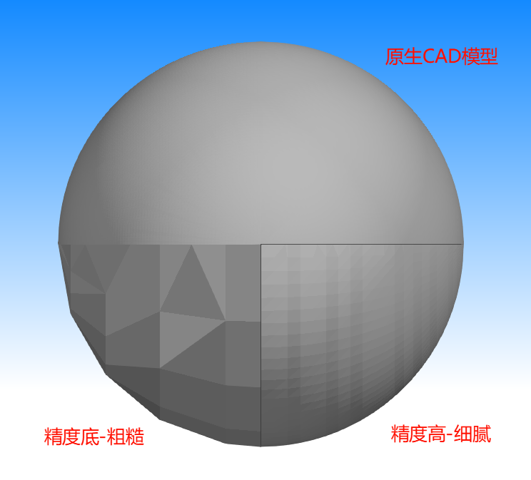
.STL is the most widely used file format for 3D printing, representing the surface of a implicit CAD model as a mesh of explicit triangles. As shown in the figure, the quality of STL drawings and the fineness of the mesh determine the lower limits of 3D printing. Generally, a finer mesh results in a smoother surface finish for the printed part and reduces post-processing time; however, it also increases the file size.
Most CAD software supports exporting as STL files. Some have selectable settings, such as "Fine" or "High", while others require users to set parameters themselves. The following introduces some common parameter settings for exporting STL files in CAD software:
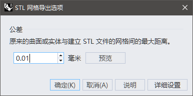
¶ Rhino:
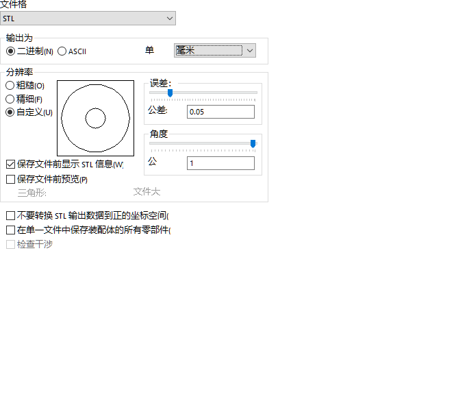
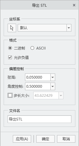
¶ SolidWorks:
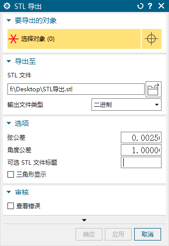
¶ NX/UG:
¶ Creo/ProE:
¶ ZBrush:
By default, the drawing accuracy is consistent with the modeling precision. Note that the export scale on ZBrush is uncontrollable, so the exported model’s size needs to be confirmed;
¶ MAYA:
By default, the drawing accuracy is consistent with the modeling precision.
¶ Cinema 4D(C4D):
By default, the drawing accuracy is consistent with the modeling precision.
¶ 3DS Max:
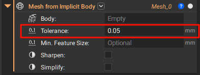
¶ nTop:
¶ Blander:
Default, the drawing accuracy is consistent with the modeling precisio