¶ Update History
| Number | Version | Update Date | What's Changed |
| 1 | V1.0 | 8/15/2023 | Initially published. |
¶ Devices, Materials and Software
Devices used
| Number | Name | Notes |
| 1 | UltaCraft Reflex (printer) | V1.2.7.10 or later |
| 2 | UltaCraft Wash (washing machine) | / |
| 3 | UltaCraft Cure (curing machine) | / |
Material used
| Number | Name | Information | Supporting Layer Thickness |
| 1 | UltraPrint-Modeling PAU10 | Modeling PAU10 | 50 μm |
| 2 | UltraPrint-Design PAM10 | Design CMYK PAM10 | 50 μm |
| 3 | UltraPrint-Modeling PAT10 | Modeling PAT10 | 50 μm |
Software used for pre-processing
| Number | Name | Version |
| 1 | Blueprint Studio | V1.0.7 or later |
Tools used in post-processing
| Number | Item | Notes |
| 1 | Pliers | |
| 2 | Art knife | |
| 3 | Sponge sandpaper | 320 grit, 500 grit, 1000 grit |
| 5 | Adhesive-backed sandpaper | 320 grit, 500 grit, 1000 grit |
| 6 | Sanding file |
¶ Design
¶ 3.1 Gap in Connections
| Connection Structure Fit Results for Different Materials | |||||
| Connection Structure | Image | Result | Gap (mm) - PAU10 | Gap (mm) - PAM10 | Gap (mm) - PAT10 |
| Ball |
|
Tend to be loose | > 0.03 | > 0.03 | > 0.02 |
| Fit | 0-0.03 | 0-0.03 | 0-0.02 | ||
| Tend to be tight | < 0 | < 0 | < 0 | ||
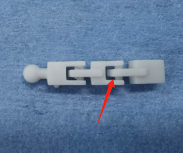
| Square column |
|
Tend to be loose | > 0.03 | > 0.03 | > 0.02 |
| Fit | 0-0.03 | 0-0.03 | 0-0.02 | ||
| Tend to be tight | < 0 | < 0 | < 0 | ||
| Round column |
|
Tend to be loose | > 0.03 | > 0.03 | > 0.02 |
| Fit | 0-0.03 | 0-0.03 | 0-0.02 | ||
| Tend to be tight | < 0 | < 0 | < 0 | ||
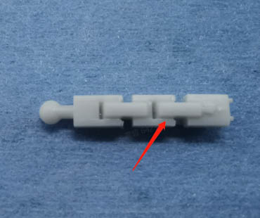
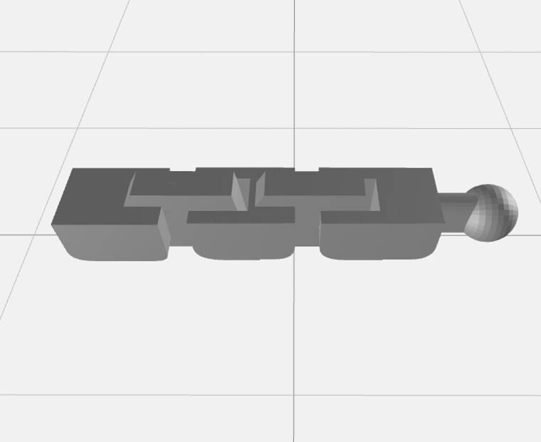
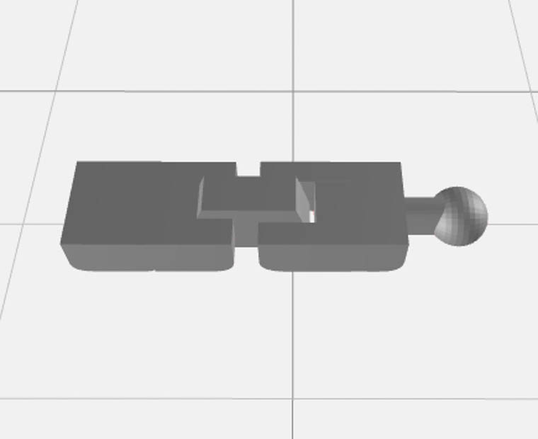
¶ 3.2 Min Gap in Moving Pieces
| Gap Test Results for Different Materials | |||||
| Gap Direction | Result | Image | Gap (mm) - PAU10 | Gap (mm) - PAM10 | Gap (mm) - PAT10 |
| XY-plane | Attached |
|
≤ 0.18 mm | ≤ 0.14 mm | ≤ 0.14 mm |
| Not attached |
|
> 0.18 mm | > 0.14 mm | > 0.14 mm | |
¶ Materials
¶ 4.1 Applications
Applications of materials
| Number | Name | Applications |
| 1 | UltraPrint-Modeling PAU10 | Inner armor |
| 2 | UltraPrint-Design PAM10 (CMYK) | Outer armor with acute angles |
| 3 | UltraPrint-Modeling PAT10 | Transparent outer armor with acute angles |
¶ 4.2 Support Parameters
| Support Parameters for Different Materials | ||||
| Support Areas | Parameter Items | PAU10 | PAM10 | PAT10 |
| Support Body | Lift Height (mm) | 5 | 5 | 5 |
| Trunk Diameter (mm) | 0.8 | 0.8 | 0.8 | |
| Overhang Angle (°) | 45 | 45 | 45 | |
| Truss Support | Lattice Size-XY | 4.5 | 4.5 | 4.5 |
| Lattice Size-Z | 6 | 6 | 6 | |
| Merge Level | 2 | 2 | 2 | |
| Support Density | Anchor Distance (mm) | 2 | 2 | 2 |
| Border Anchor Distance (mm) | 2 | 2 | 2 | |
| Connection | Top Diameter (mm) | 0.34 | 0.32 | 0.32 |
| Connection Length (mm) | 1.5 | 1.5 | 1.5 | |
| Contact | Contact Shape | Sphere | Sphere | Sphere |
| Diameter (mm) | 0.46 | 0.46 | 0.46 | |
| Embedded Depth (mm) | 0.25 | 0.25 | 0.25 | |
¶ 4.3 Washing Settings
| Washing Parameters for Different Materials | ||||
| Number | Name | Washing Speed | Cleaning Solution | Washing Time |
| 1 | UltraPrint-Modeling PAU10 | 180 r/min | 95% alcohol | 2min rough wash + 2min fine wash |
| 2 | UltraPrint-Design PAM10 (CMYK) | 180 r/min | 95% alcohol | 2min rough wash + 2min fine wash |
| 3 | UltraPrint-Modeling PAT10 | 180 r/min | 95% alcohol | 2min rough wash + 2min fine wash |
¶ 4.4 Curing Settings
| Curing Parameters for Different Materials | ||||
| Number | Name | Heat or Not | Curing Agent | Curing Time |
| 1 | UltraPrint-Modeling PAU10 | No | Air | 30 min |
| 2 | UltraPrint-Design PAM10 (CMYK) | No | Air | 15 min |
| 3 | UltraPrint-Modeling PAT10 | No | Air | 10 min |
¶ Pre-Processing Procedures & Parameters
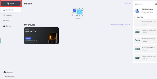
¶ 5.1 Create Cloud Projects
Open Blueprint Studio, enter “Slicer” and create a new project. If failing to create, delete an existing project and try again.
 |
 |
| Slicer on Blueprint Studio | Creating a new project on Blueprint Studio |
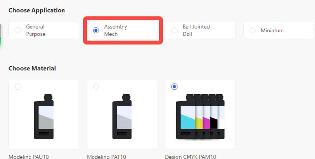
¶ 5.2 Set Parameters
Set the project parameters according to your needs. Then enter the slicer page by hitting ‘Confirm’.
 |
 |
| Choosing application on Blueprint Studio | Slicer page on Blueprint Studio |
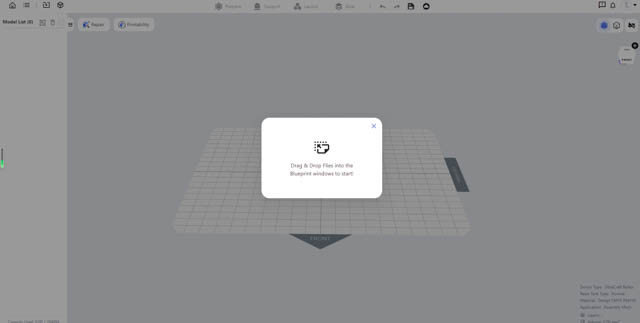
¶ 5.3 Import Models
Import models by hitting the import icon or dragging the files into the page.
 |
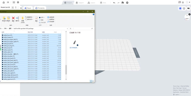 |
| Importing models | Dragging to import |
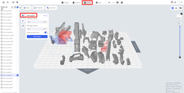
¶ 5.4 Layout
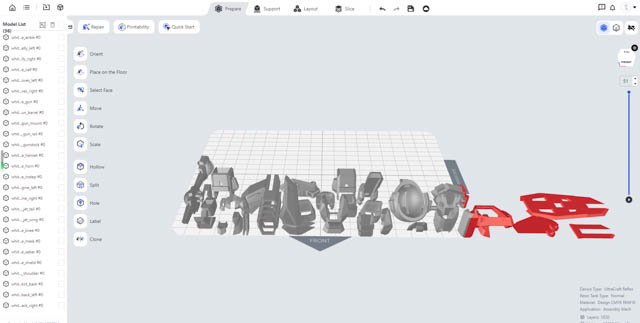
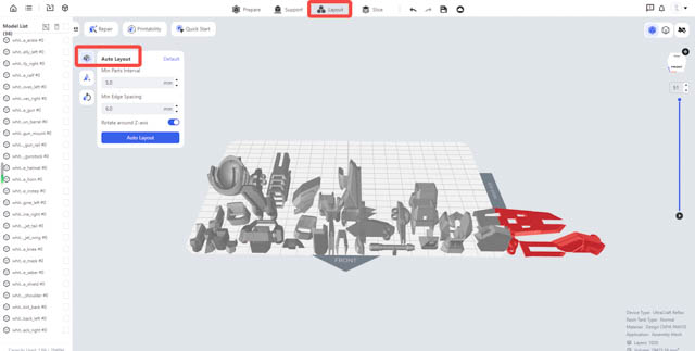
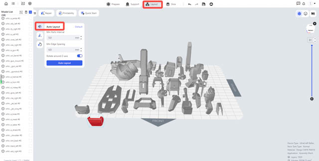
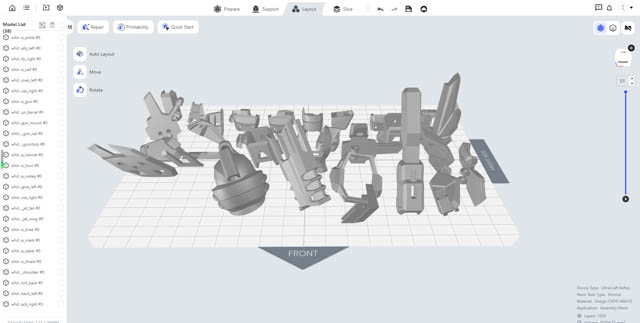
Hit ‘Layout’ > ‘Auto-layout’ to perform layout. (Min parts interval > 5 mm. Min edge spacing ≥ 6 mm.)
 |
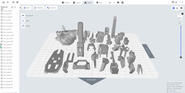 |
| Auto-layout | Auto-layout result |
¶ 5.5 Prepare
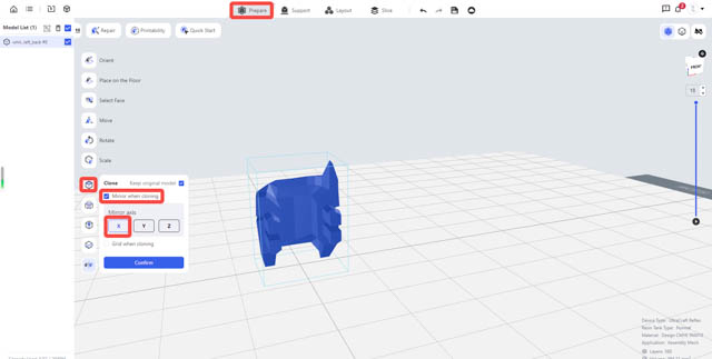
Certain models may need mirroring, cloning, labeling and so. For these, you may go to ‘Prepare’ section.
(1)Below is an example presenting ‘Mirroring when cloning’ feature. (Select the model to mirror, hit Clone > Mirror when cloning > Mirror axis - X > Confirm, and a right hand is generated by mirroring the left hand.)
 |
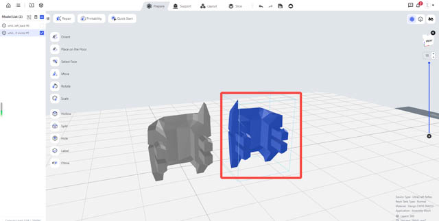 |
| Mirroring when cloning | Mirroring result |
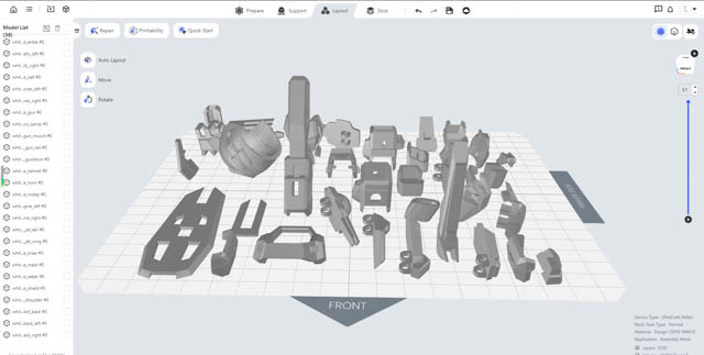
(2)Perform a second layout to get the models prepared for supports. (Min parts interval > 5 mm. Min edge spacing ≥ 6 mm.)
 |
 |
¶ 5.6 Placement
Enter ’Prepare’ section, adjust the models with ‘Move’, ‘Rotate’ and ‘Select’ tools according to some rules (characteristic parts and acute parts facing up, opening facing down, as few supports as possible and so on). More details are as follows.
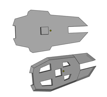
(1)General rule:
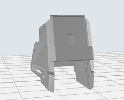
- Characteristic parts - facing upward, to ensure the finish quality of the details;
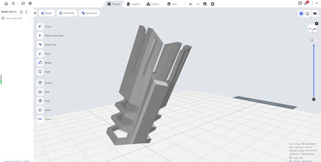
- Parts with beam structures - inclined (60° with the floor), to ensure a flat and smooth beam surface;
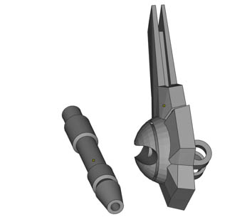
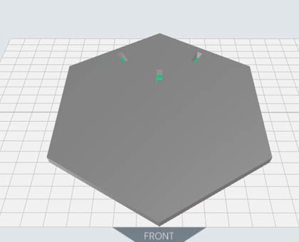
- Solid bars and large flat surfaces - inclined (30°-45° with the floor), to ensure the printability of the structures.
| Helmet | Barrel shroud with beam structure | Waist with beam structure | Solid bar | Large flat surface |
 |
 |
 |
 |
 |
 |
 |
| Part with beam structures inclined at 60° | Part of large flat surface inclined at 45° |
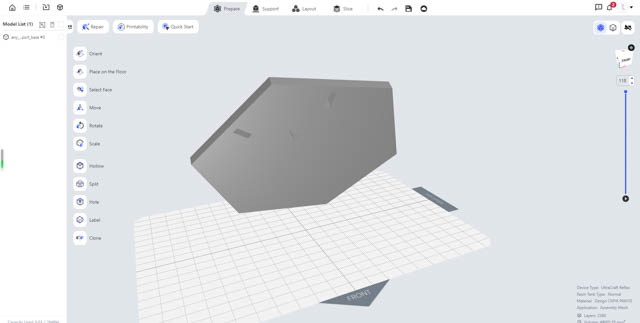
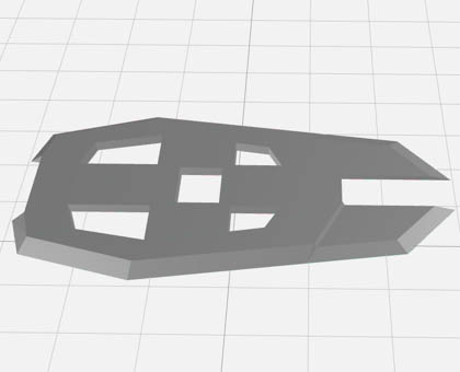
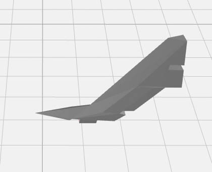
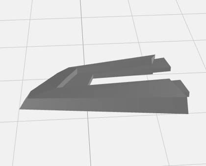
(2)Acute parts: Acute sides should avoid facing downward. Otherwise, the angles may become obtuse or missing after printing.
| Shield with acute angles | Tail wing with acute angles | Skirt armor with acute angles |
 |
 |
 |
 |
 |
| Acute angles facing downward to be adjusted | After adjustment |
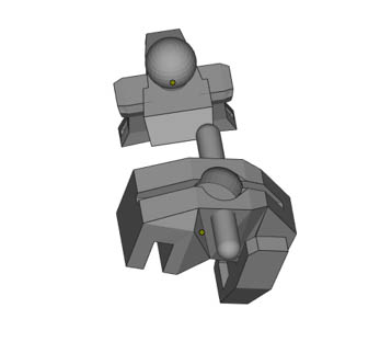
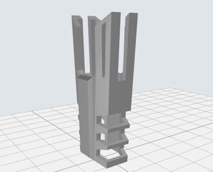
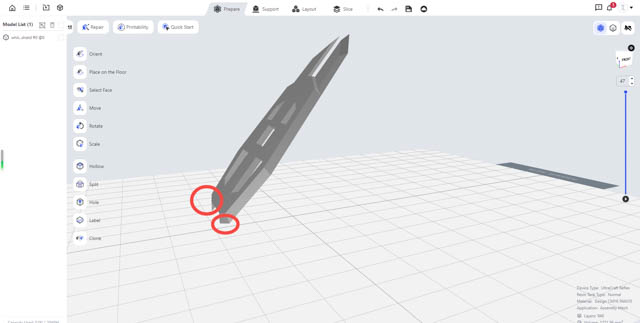
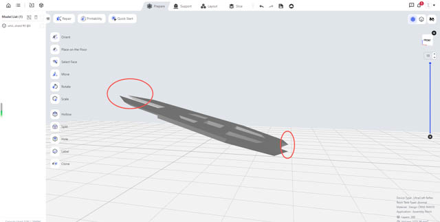
(3)One-piece moving parts: Parts like these need to be placed horizontally to ensure their movability. Otherwise, the buckles, joints or locks might attach together as their gaps and slits are small.
| Moving finger in one piece | Moving thumb in one piece |
 |
 |
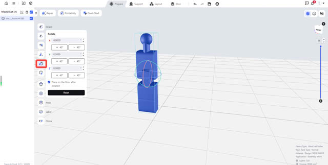 |
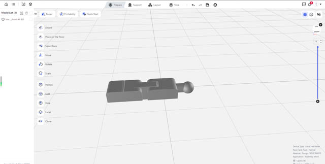 |
| Placing the model so the slits are perpendicular to the floor | Slits perpendicular to the floor |
(4)Perform a second layout to get the models prepared for supports. (Min parts interval > 5 mm. Min edge spacing ≥ 6 mm.)
 |
= |
| Performing second layout | Second layout result |
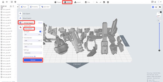
¶ 5.7 Support
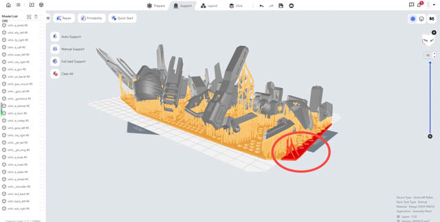
a.Auto-Support: Enter ‘Support’ section. By clicking ‘Full-Bed Support’, you may add supports to them and a base connecting their supports. Click ‘Full-Bed Support’ > ‘Truss Support’ and generate supports.
 |
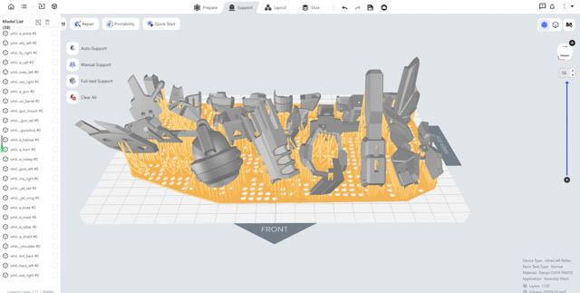 |
| Generate full-bed supports | Full-bed support result |
b.Edge detecting: If any model or the support base extends beyond the floor's edge, you may go ‘Layout’ > ‘Auto-layout’ to change the min edge spacing accordingly and then re-generate supports.
 |
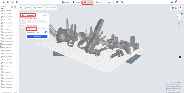 |
| Support base beyond the floor | Changing min edge spacing |
¶ 5.8 Slicing
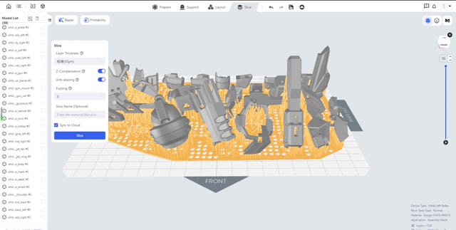
(1)Go to ‘Slice’ section and perform slicing with default parameters.
 |
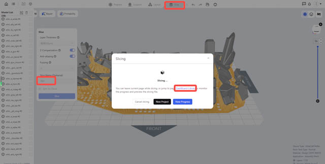 |
| Slice | Slice files |
(2)After slicing is done, you may check slice files and send print jobs at [Slice Files] page.
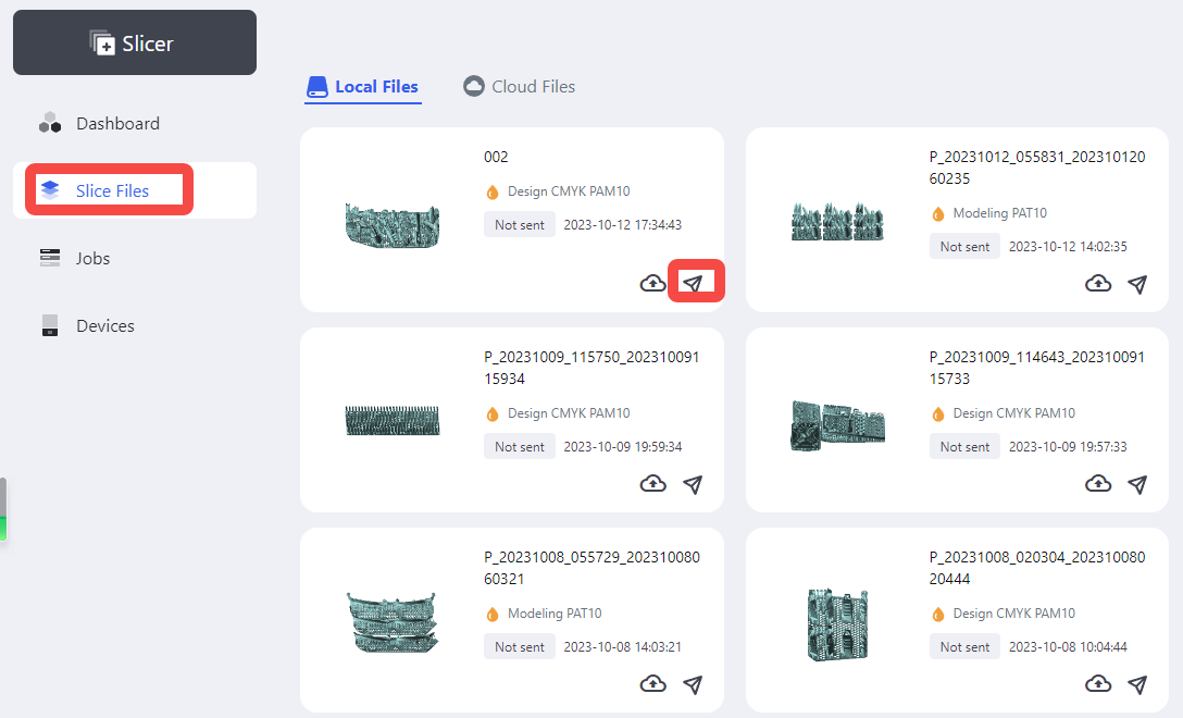
¶ Printing Process
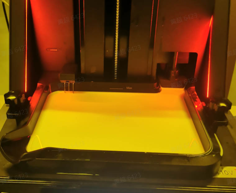
¶ 6.1 Printing
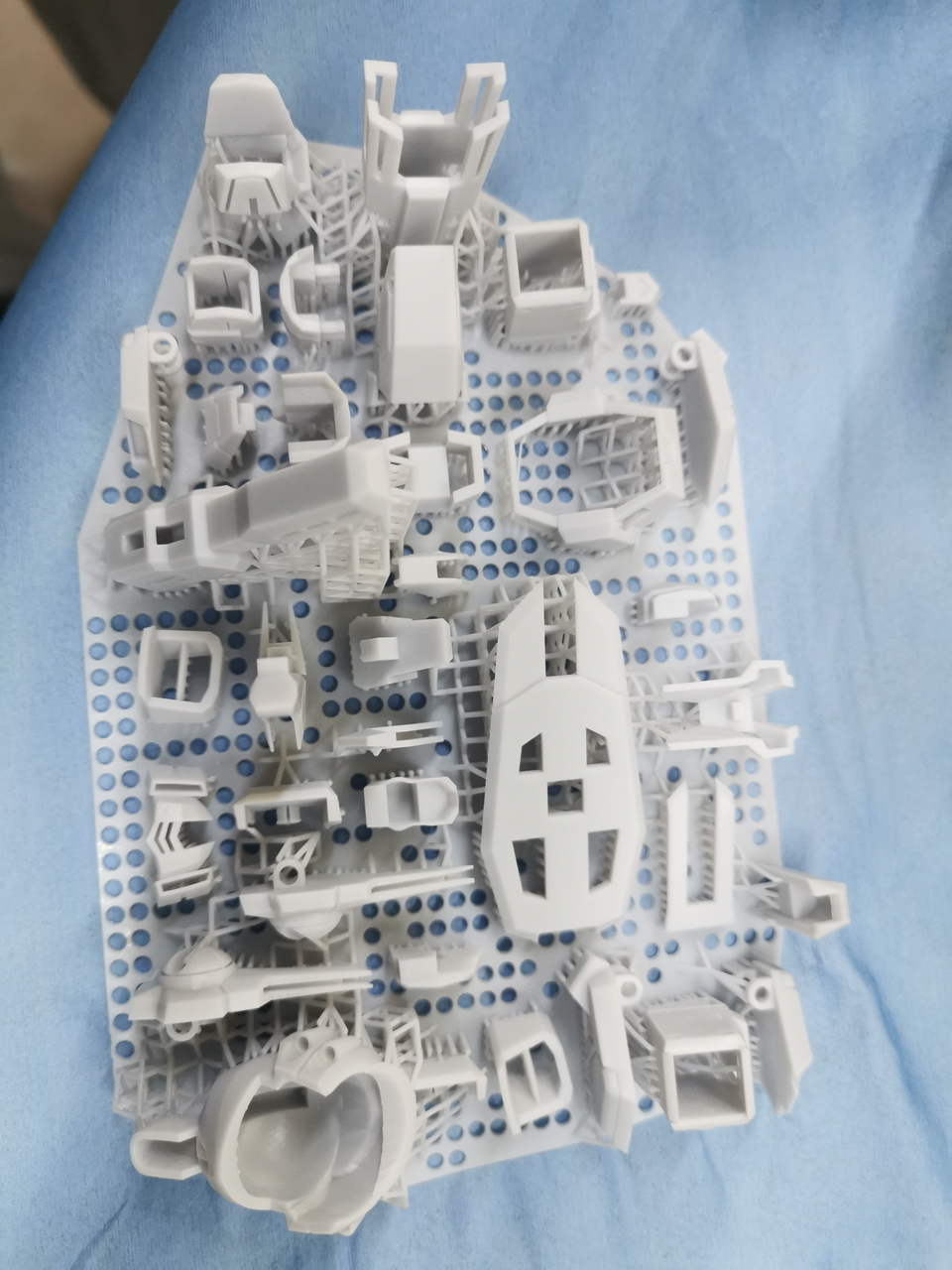
Send the slice files to your printer on Blueprint platform, or import them to your printer via USB flash drive. Insert the resin cartridge and start printing.
 |
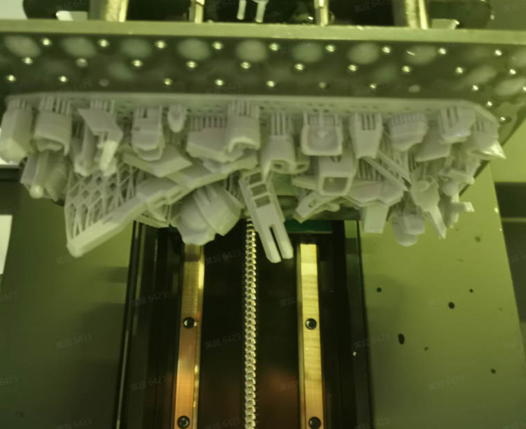 |
| Printing | Print result |
¶ Pre-Processing Procedures
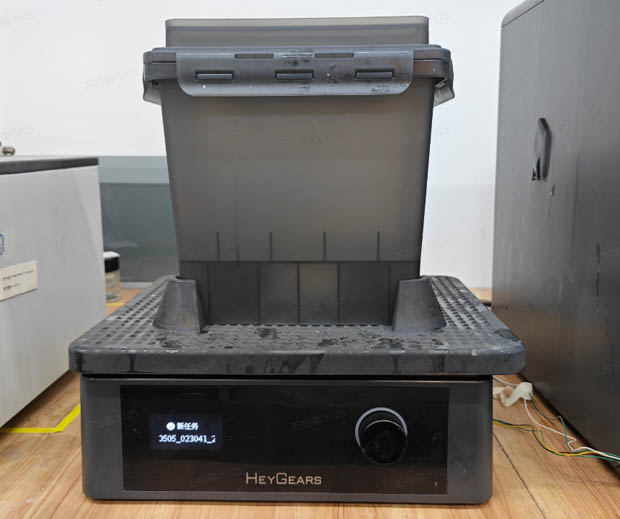
¶ 7.1 Washing
(1)Set the washing settings on UltraCraft Wash or Blueprint platform when sending wash jobs.
(2)Put the printed models in a UltraCraft Wash boxes, submerge them with 95% alcohol.
 |
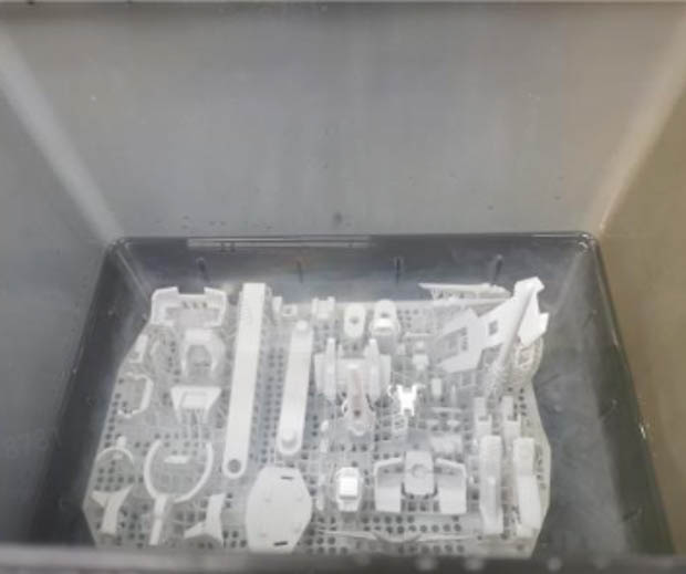 |
| UltraCraft Wash | Before washing |
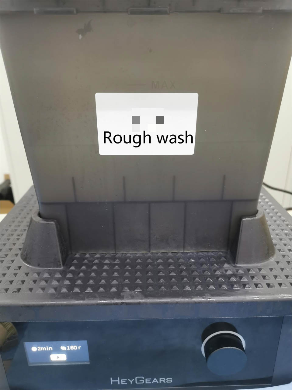
(3)It's recommended to wash the print models twice:
- a rough wash with used 95% alcohol, to wash off most of the uncured resin on the models;
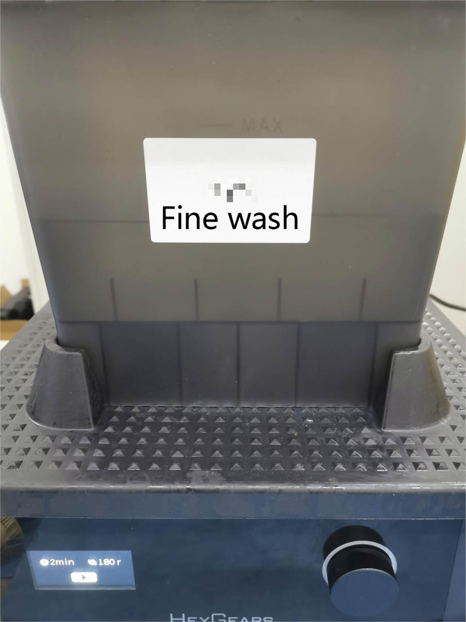
- a fine wash with new 95% alcohol, to clean the rest resin.
 |
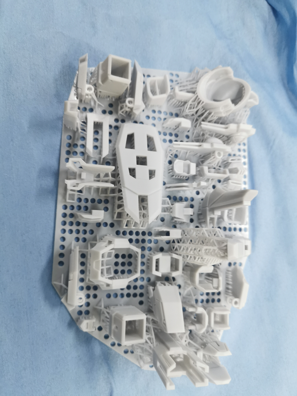 |
| Rough wash box | After rough wash |
 |
 |
| Fine wash box | After fine wash |
(4)After washing, blow dry or air dry the models.
¶ 7.2 Remove supports
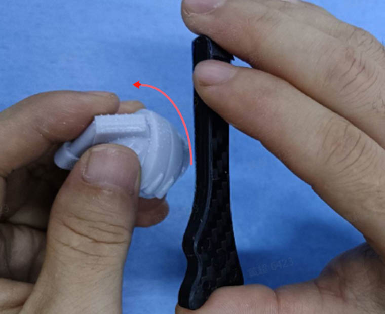
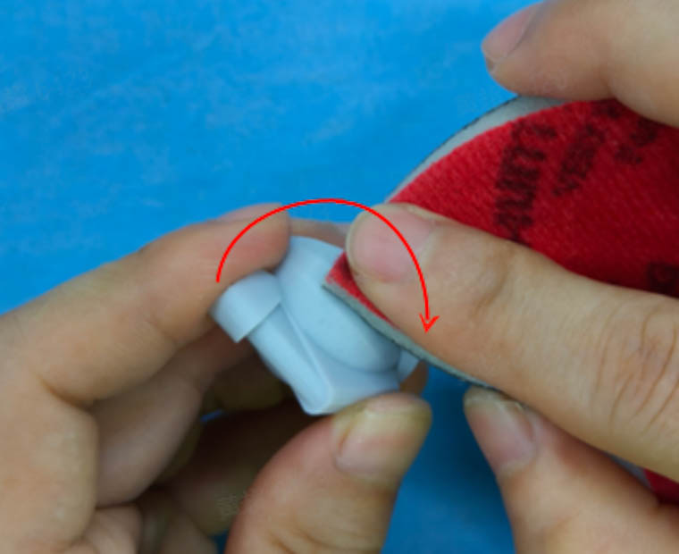
(1)For most models, removing by hand will be fine (twisting off the support structures).
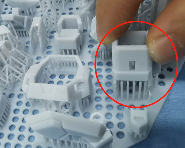 |
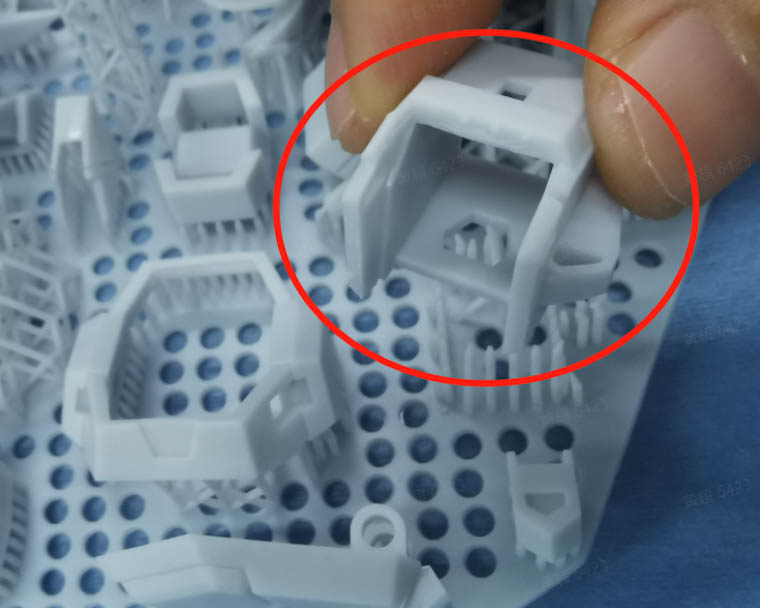 |
| Removing by hand | Result |
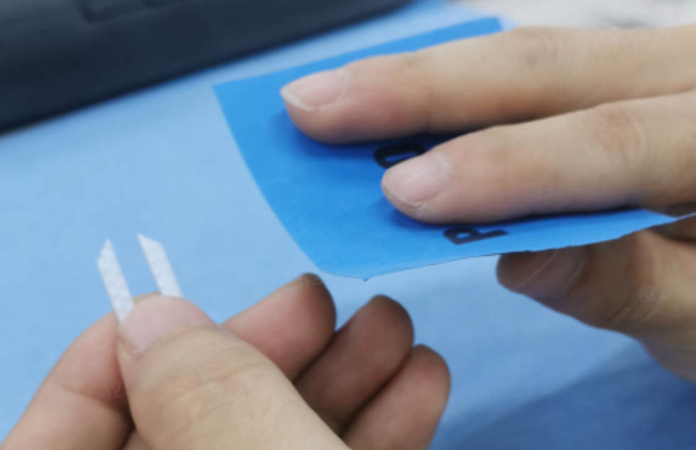
(2)For models with thin walls, it's better to remove with tools (pliers or art knife).
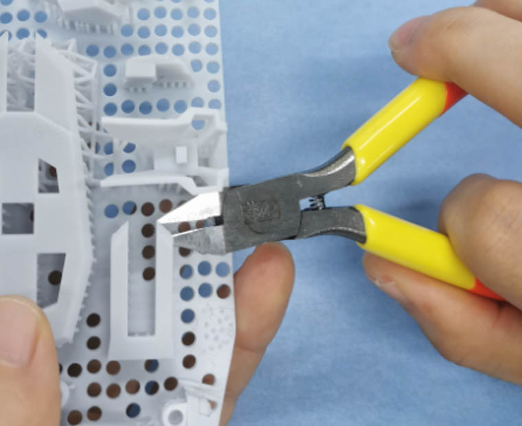 |
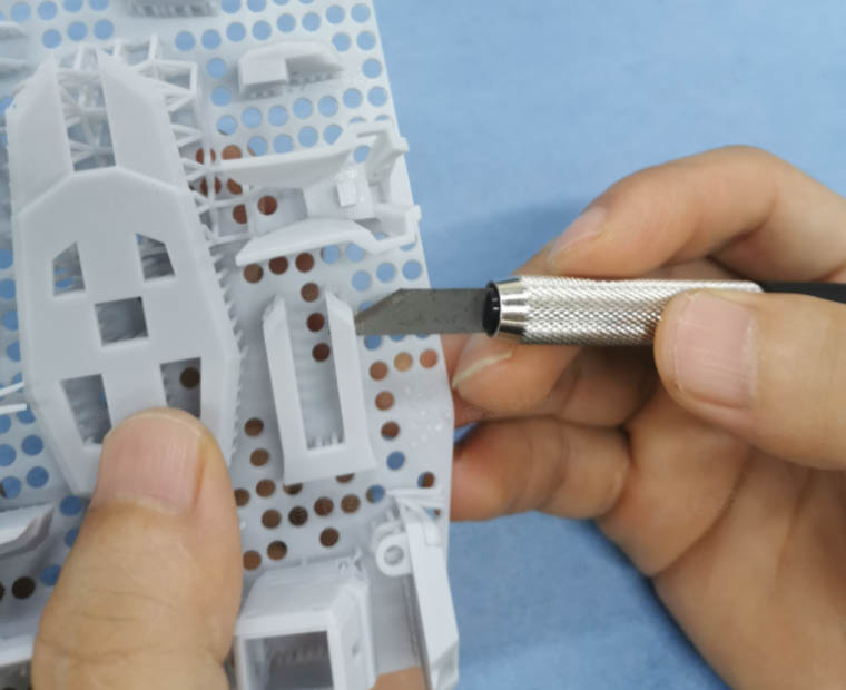 |
| Removing with pliers | Removing with art knife |
¶ 7.3 Curing
(1)Set the curing settings on UltraCraft Cure or on Blueprint platform when sending curing jobs.
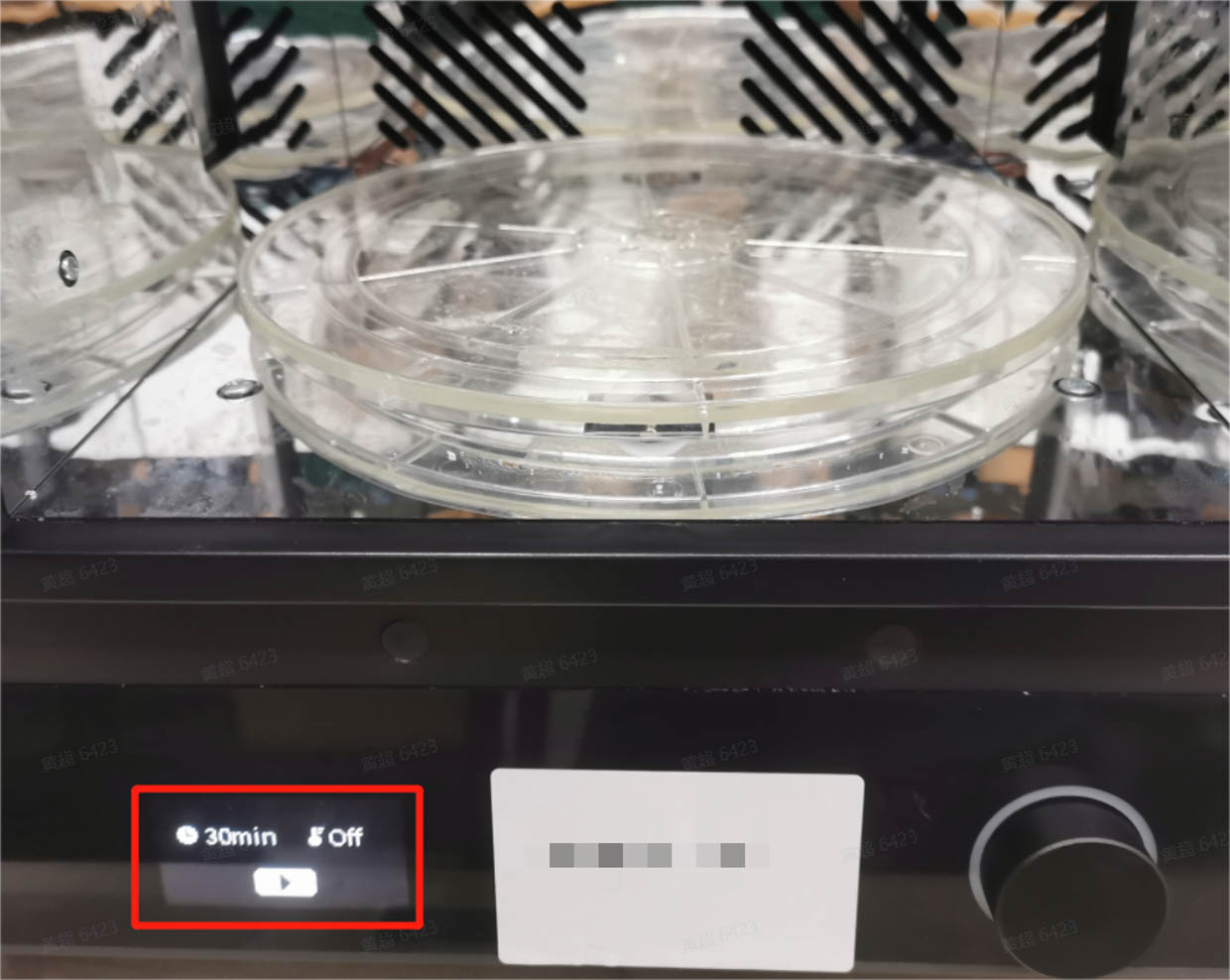
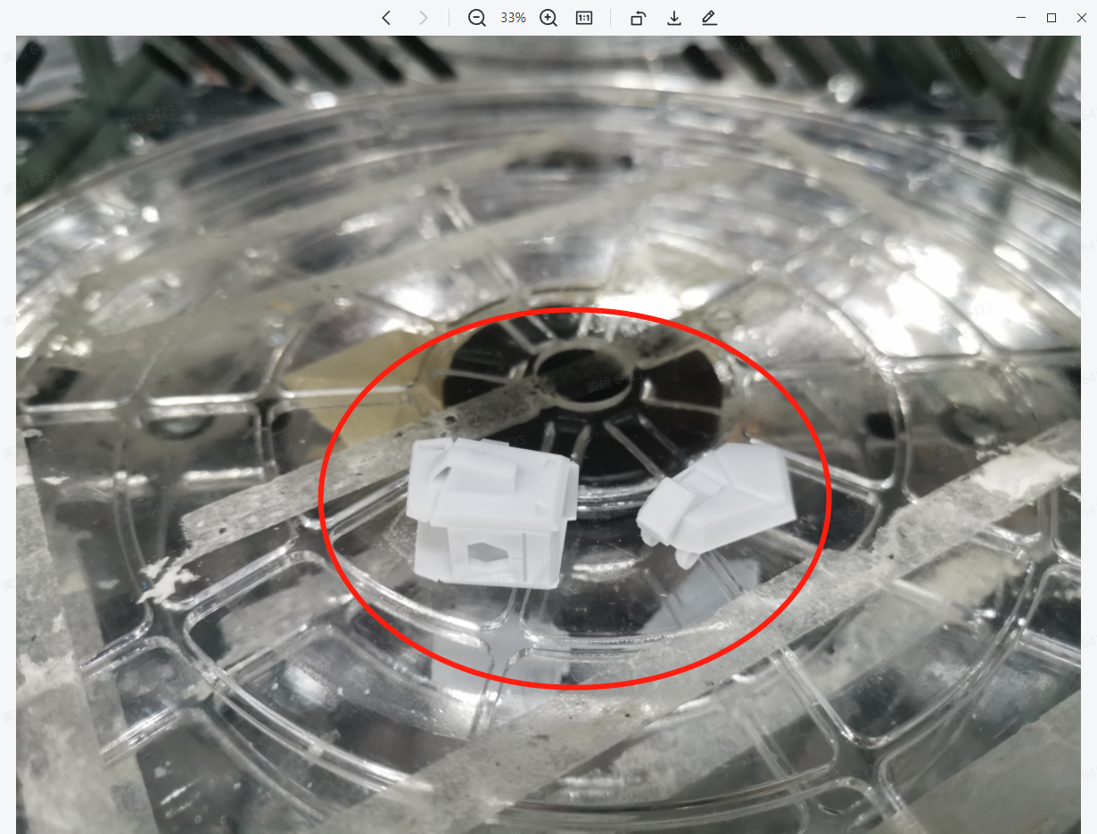
(2)Most models can be directly placed in UltraCraft Cure to be cured.
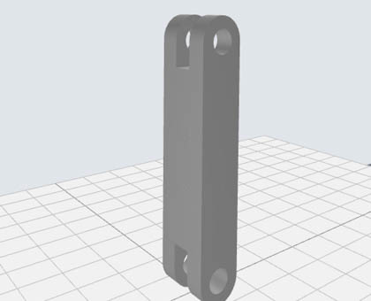
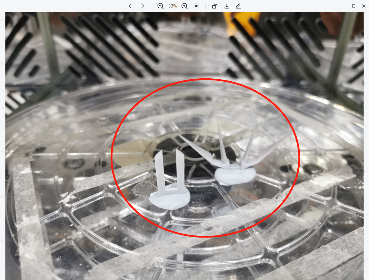
(3)Models with bars or planks need to be stuck upright in the curing machine with blue-tack or plasticine, so to lower the risk of deformation.
¶ 7.4 Polish
(1)Most models can be polished with tools starting from 300-400 grit, to 600 grit, then 1000 grit. Polishing till 1000 grit is suggested for models to be coated.
(2)Models with thin walls are recommended to start from 500-600 grit, lowering the risk of damage.
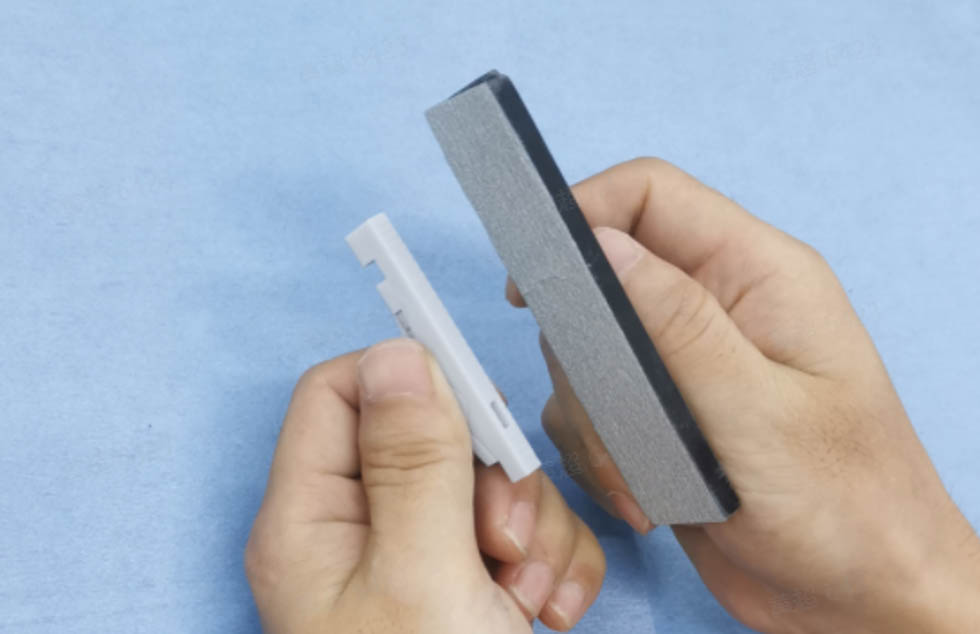
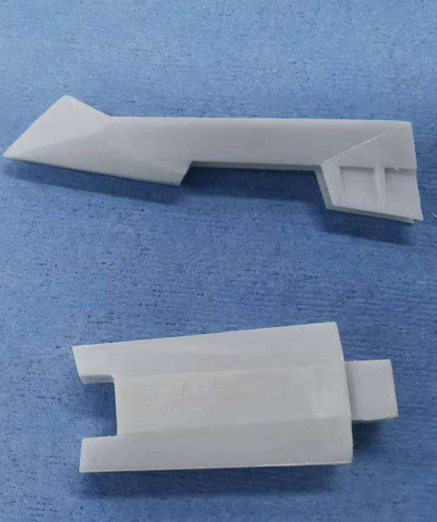
(3)For models with flat surfaces, it’s recommended to polish in one direction with a sanding file parallel and close to the flat surface, lowering the risk of damage any side.
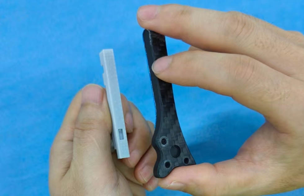
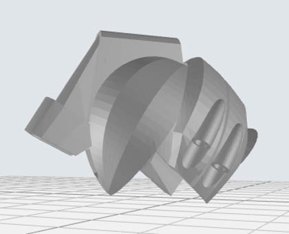
(4)For models with curved surfaces, it’s recommended to polish around the curved surface in one direction with a 320 grit sanding file first (the file needs to be hard and flat enough so not to damage other areas), then polish the curved surface in circles with a 600 grit sandpaper to give a more even force reducing scratches.
 |
 |
| Polishing around curved surface in one direction with sanding file | Polishing curved surface in circles with sandpaper |
¶ 7.5 Finished parts
 |
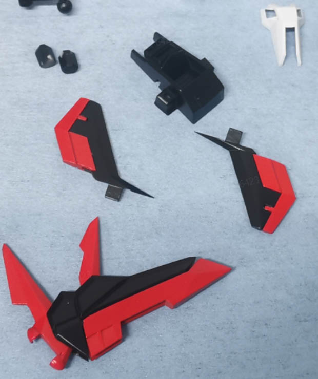 |
| 3D printed mecha parts after polishing | 3D printed mecha parts after coating |