¶ Print Process Editor (Open Material) Feature Explained
Print Process Editor (PPE) is a new-generation 3D printing parameter control feature introduced by Blueprint Studio (BPS) based on the Open Material Mode. Unlike traditional slicing software's completely open but device‑protection‑lacking generic parameter model, BPS adopts an intelligent and protected open strategy (Intelligent, Protected Openness). Through layered parameter control, PPE ensures the usability of third‑party resins while maximizing compatibility with official preset adaptive/intelligent process strategies, thereby safeguarding equipment safety and reducing trial‑and‑error costs. Users typically only need to appropriately adjust exposure parameters to be compatible with most 405nm‑wavelength UV resins on the market.
It should be noted that currently only the most critical subset of parameters (Basic Mode) is open, supporting the Reflex RS and Reflex RS Turbo models. Support for other models in the Reflex series, as well as the Expert Mode (which offers nearly full control over advanced parameters and process strategies but is mutually exclusive with official preset adaptive/intelligent process strategies), is still under development and testing.
This document mainly introduces the functions of PPE, the meaning of each currently open parameter item, and provides device‑aware testing and adjustment recommendations.
¶ 1. Slicer - Project Setup
 |
 |
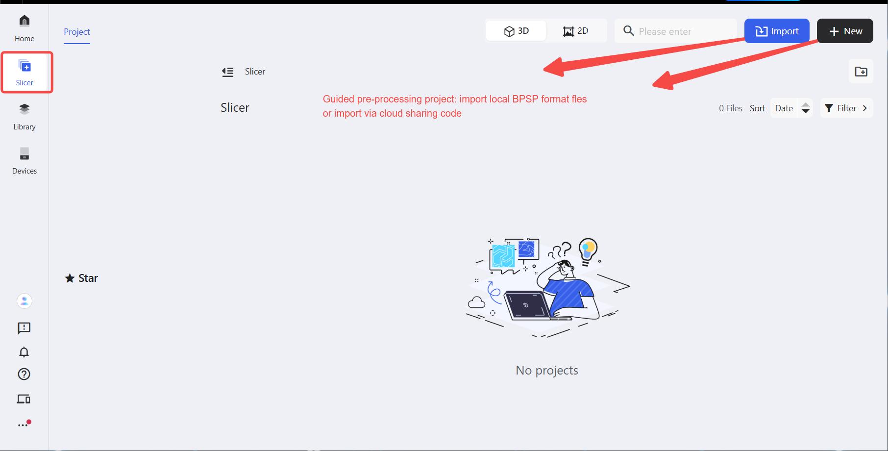
Click the slicer, create a new project (click Import - locally saved BPSP file / cloud sharing code or New - local/cloud implementation), select setup such as the corresponding device type, and then enter project.
¶ 2. Slicer - Project
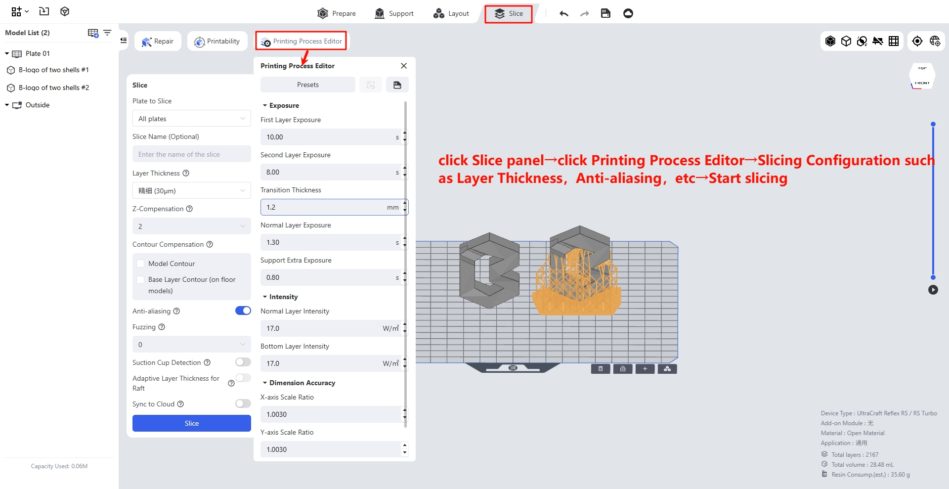
¶ 2.1 Slice - Print Process Editor
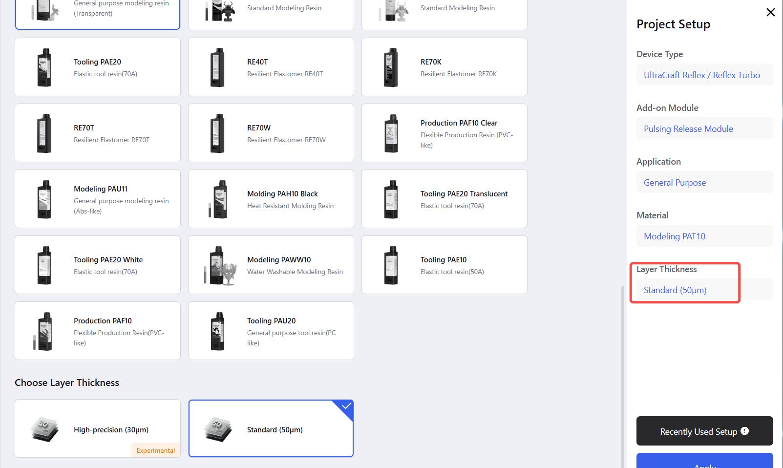
Unlike the complex parameter lists of traditional software, BPS provides intelligent recommendations and device-adapted default values based on material types. You can modify the preset configuration or click the save icon next to the preset configuration to apply one-click parameter modification to the saved configuration.
¶ 1. Exposure Time
- First layer exposure time:
-
The exposure time of the first layer of the slice, which controls the curing degree of the first layer of the material to achieve different bonding strengths with the build platform.
-
It is recommended to set the first layer exposure time to ten times that of the regular layers. If the value is too high, the adhesion between the print's bottom and the build plate will be excessively strong, making it hard to remove the prints. If the value is too low, the adhesion will be insufficient, which may cause the print's bottom to fall off during first-layer printing or in the subsequent peeling process.
- Second layer exposure time:
-
The exposure time for the second sliced layer. Since the penetration depth of UV light may exceed the thickness of a single layer, this helps control the adhesion between the model bottom and the build plate. Transition layers start from this layer.
-
It is recommended to keep it consistent with the first layer exposure time, and it can be decreased when the prints are difficult to scrape off (adjusting in 1-second increments is recommended).
- Transition layer counts:
-
The number of smooth transition layers from the second layer to regular layers. The exposure time changes linearly with the increase of layers, which is used to reduce the risk of interlayer cracking caused by different exposure durations and minimize layer lines as well as the elephant's foot effect.
-
Increasing this value improves adhesion, while decreasing it speeds up printing speed. Default settings are recommended (e.g., set to 20 for a layer thickness of 0.05mm, and 30 for a layer thickness of 0.033mm, and 10 for a layer thickness of 0.1mm).
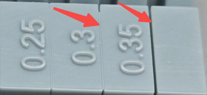
- Regular layer exposure time:
- The part above the transition layers is treated as regular layers. This parameter is used to adjust the curing degree of regular layers and must be set accurately according to the photosensitive properties of materials. Although this parameter can be adjusted freely, the built-in boundary detection mechanism of the software will mark abnormal values to ensure the printing success rate.
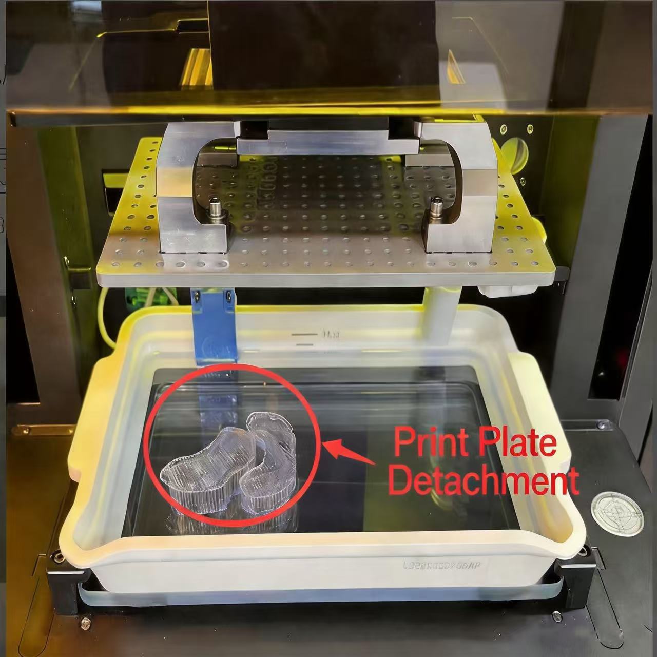
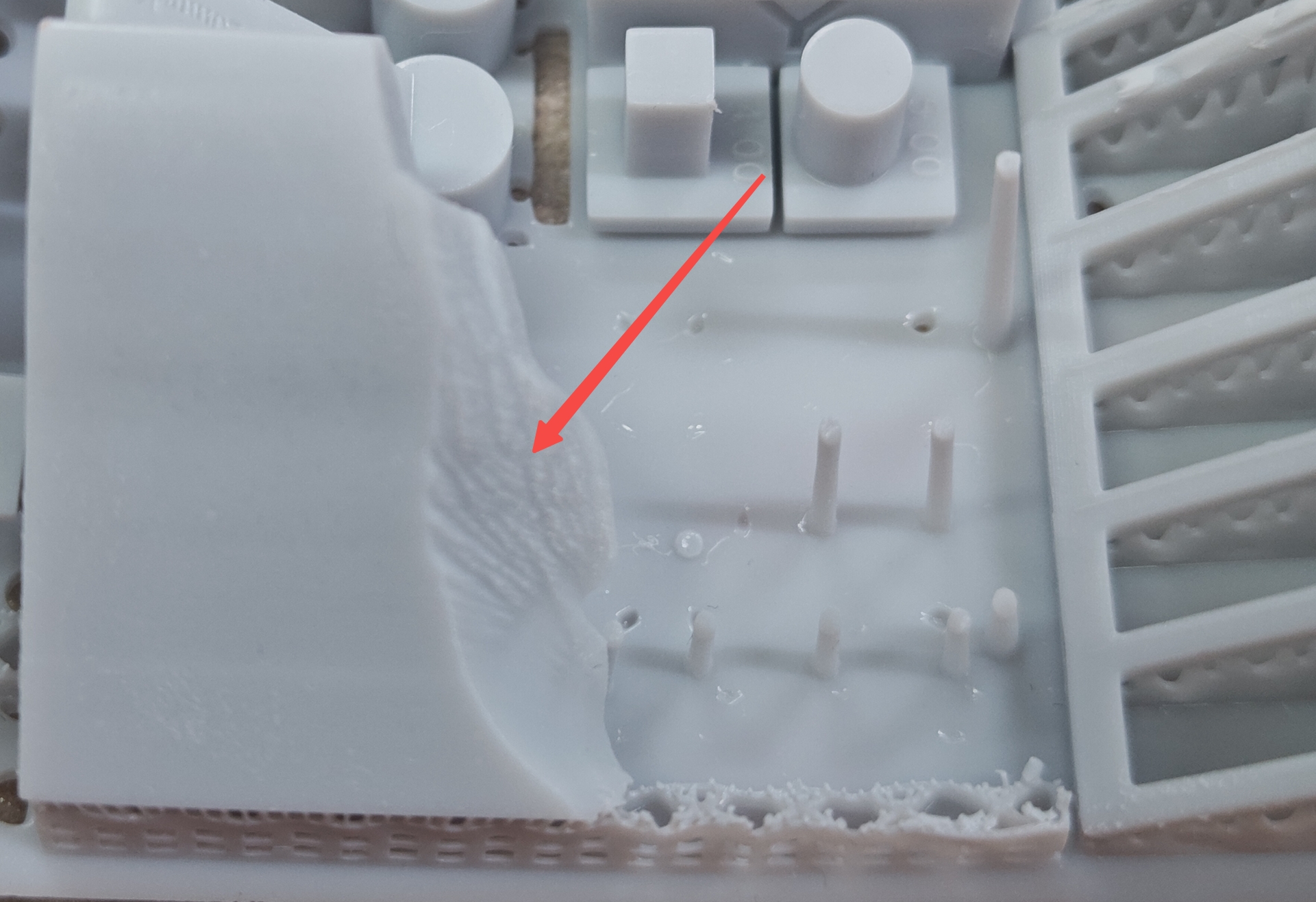
- Overexposure causes blocked holes and adhesion; underexposure leads to defects or plate detachment.
| Overexposure may cause gap adhesion | Underexposure leads to detail forming failure, overly soft supports, insufficient strength, and upper layer peeling failure |
 |
 |
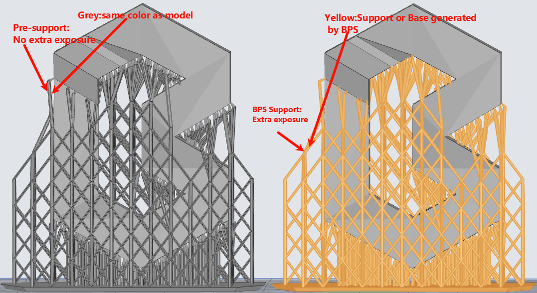
- Support extra exposure time:
- Specially used for additional curing of support structures. If the value is too high, the support structures will become overly stiff and difficult to peel off and remove; if it is too low, the structures may deform or even tear during peeling, resulting in printing failures. It is recommended to set 1 second or longer for flexible resins, and 0.5 to 1 second for hard resins. This function is only applicable to support structures generated by the software itself.
| Pre-supported model vs BPS support model |
 |
¶ 2. Intensity
- Regular layer intensity:
-
This parameter adjusts the UV light intensity of regular layers, which can optimize the curing performance and detail forming capability of the used resin, shorten printing time and reduce residues and so on.
-
It should be set accurately according to the photosensitive properties of the resin used. For Reflex RS series printers, light power is safely limited to 12.0-17.0 W/㎡ to protect device longevity.
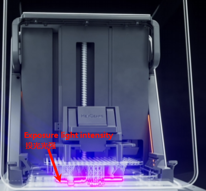
- Bottom layer intensity:
-
The bottom layer refers to the part below the regular layers. This parameter adjusts the UV light intensity of the bottom layer, which is mainly used to control the adhesion firmness between the print's bottom part and the build plate.
-
It is recommended to adjust it in conjunction with and according to the photosensitive properties of the resin in use. If the prints adheres too tightly and is hard to remove, lower the value appropriately; if it is prone to edge warping and falling off, raise the value properly. For Reflex RS series printers, the light intensity is safely limited within the range of 12.0 - 17.0 W/㎡ to extend the service life of the equipment.
¶ 3. Dimensional Accuracy
Rather than adjust by shrinkage/tolerance compensation which uses percentage scaling or inner/outer diameter adjustments, BPS offers more granular axial control. Actual model theoretical size = coefficient of each axis * size of each axis. This scaling can be adjusted slightly to optimize the dimensional deviation of the actual printed model, and the default value is generally used. If dimensional deviation occurs in a specific axis during printing, the coefficient value of that axis can be modified. When combined with contour compensation, a more flexible adjustment range and more accurate dimensional precision control can be achieved.
- Z Complement:
- Adjustable range [0, 5], where the value represents the number of layers. Compensates for the loss of details in the Z-axis direction caused by light penetration. When enabled, it can improve dimensional accuracy, and generally the default setting can be used, but it may affect the printing effect of some fine structures. If a circular hole is compressed into an ellipse in the X/Y direction, adjust it higher; if it is stretched into an ellipse in the Z direction, adjust it lower.
- X/Y/Z-axis scaling factor:
- Consistent with the scaling function but with finer adjustment [0.9000, 1.1000]. Actual model theoretical size = coefficient * size.
- Contour Compensation:
-
Process the model contour to achieve model size compensation, reducing size expansion or contraction. Contour compensation mainly addresses the potential overall dimensional tolerance issues that may occur when 3D printing large-sized models using light curing, while bottom layer contour compensation mainly addresses the elephant foot problem at the bottom of the model. Use as needed (only enable when relevant issues arise; it is not recommended to enable if no issues occur). Contour Compensation can be paired with model scaling to more freely adjust the model size.
-
Model Contour:
Takes effect on every sliced layer globally, range [-10,10]. Recommended value is -0.1 for large models.
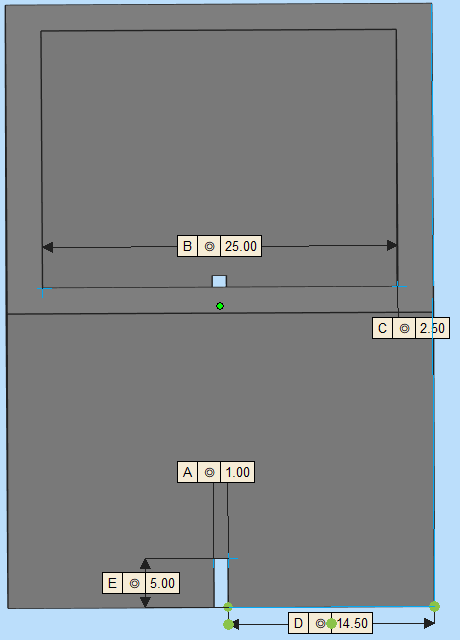
- Bottom layer contour:
Only effective for the base layer (default 1mm) to address the elephant foot problem, recommended value is -0.2.
 |
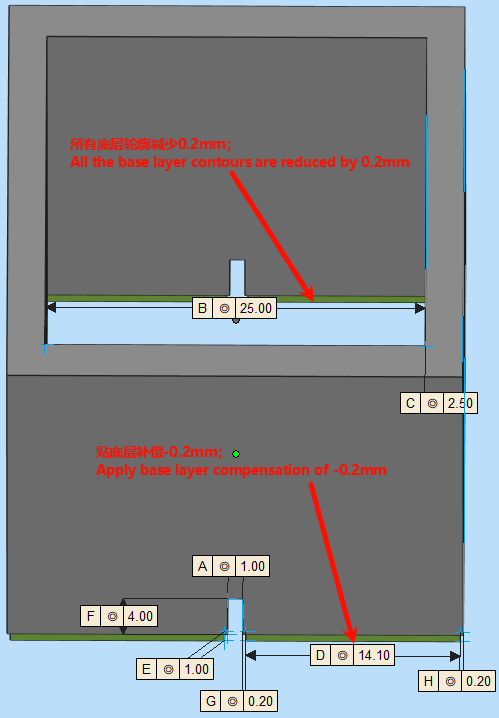 |
Bottom layer contour compensation value -0.2mm (14.5mm → 14.1mm)
¶ 4. Detail Reproduction
BPS Basic Mode offers standard grayscale levels designed to balance surface smoothness and device processing performance.
- Anti-aliasing Toggle:
In most cases keep it on. It smooths the jagged edges of sliced images, making surfaces smoother but potentially affecting the sharpness of fine details.
| AA off with Blur off(side surface) | AA on with Blur off(side surface) |
 |
 |
- Image Blur:
Adjustable values 0/2/4, default recommended. Higher levels distribute edge pixel grayscale more evenly, reducing layer lines and ripples.
| AA on with Blur 0(side surface) | AA on with Blur 4(side surface) |
|
 |
¶ 5. Other Intelligent Process Strategy
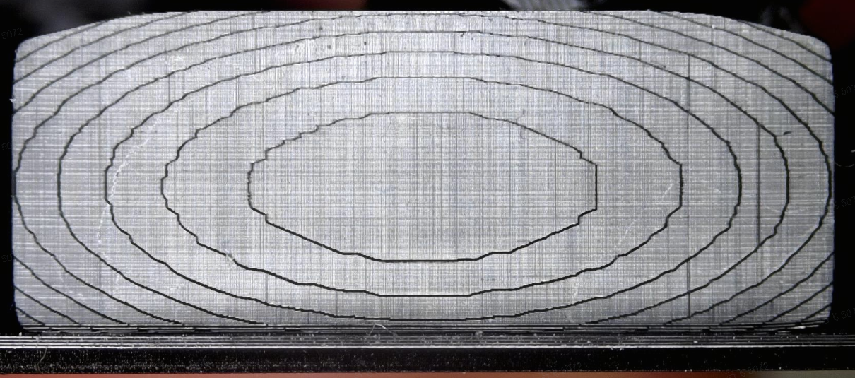
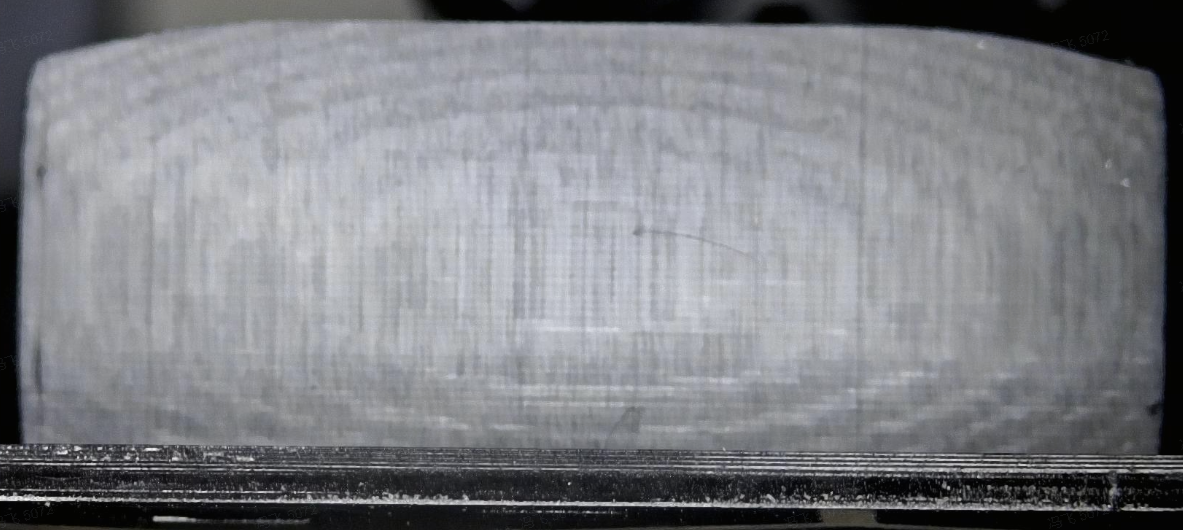
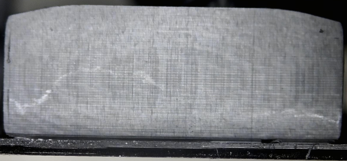
- Suction cup process:
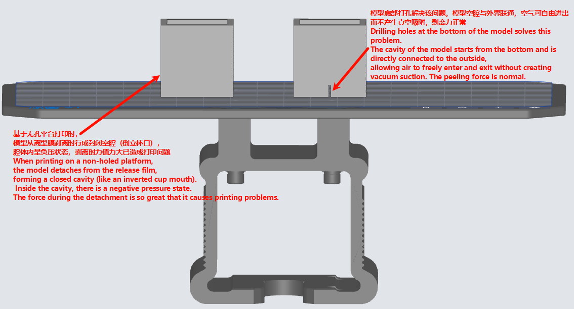
One of BPS's advanced strategies. Automatically recognizes models during slicing to break closed cavities without manual punching. Significantly reduces the suction cup effect during peeling.
If the built-in process supports the suction cup process strategy, it can be enabled; if not, it cannot be selected for enabling.
Enabling suction cup process (also known as closed cavity detection in the market), the recognition model automatically adopts image strategies during software slicing to break through closed cavities without manual punching, significantly reducing the impact of the suction cup effect caused by suction cups (closed cavities) during model printing and peeling, avoiding depressions, ripples, deformation, and even plate detachment, thereby achieving better surface effects. However, it may also significantly extend the time required for slicing and printing (only detecting suction cup structures with a volume ≥ 10mm³).
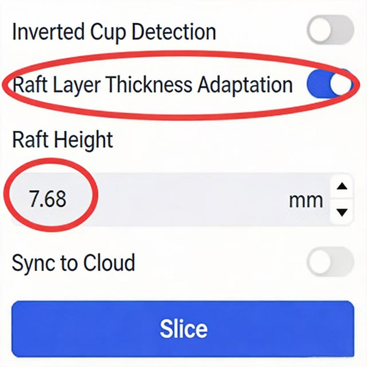
- Bottom Layer Thickness Self-Adaptation:
Enables the bottom layer thickness to adaptively increase, improving overall print speed and resisting layer-eating issues. It is recommended to use the intelligently recommended default values.
It can be enabled if the built-in process supports this strategy. It mainly enables the layer thickness below the raft segment/set height segment to adaptively increase, in conjunction with the self-adaptation strategy to improve the overall printing speed, address the issue of peeling failure on the upper/lower side of large rafts, and mitigate the common layer-eating problem (decrease in Z-axis height) in LCD light curing, etc. However, there are also risks: there is a risk of slight horizontal streaks within the raft height range. The adjustable range is (0, 999), and it is recommended to use the default value or adjust according to the following guidelines after specific issues occur.
-
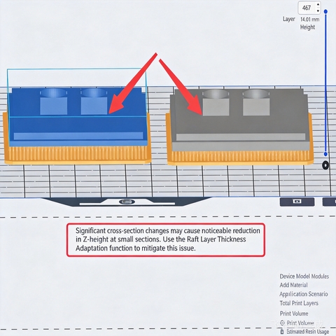
Set the raft height. Under normal circumstances, the raft height is set to the thickness of 1.0mm to 1.5mm. If there are requirements for speeding up printing or if the model has obvious cross-sectional changes (which may cause the Z-direction height of the structure at the cross-sectional change of the printed model to be significantly reduced), the raft height can be custom-set to the height at the cross-sectional abrupt change (as shown in the figure below, slide the layer height axis on the right to find the corresponding height);
-
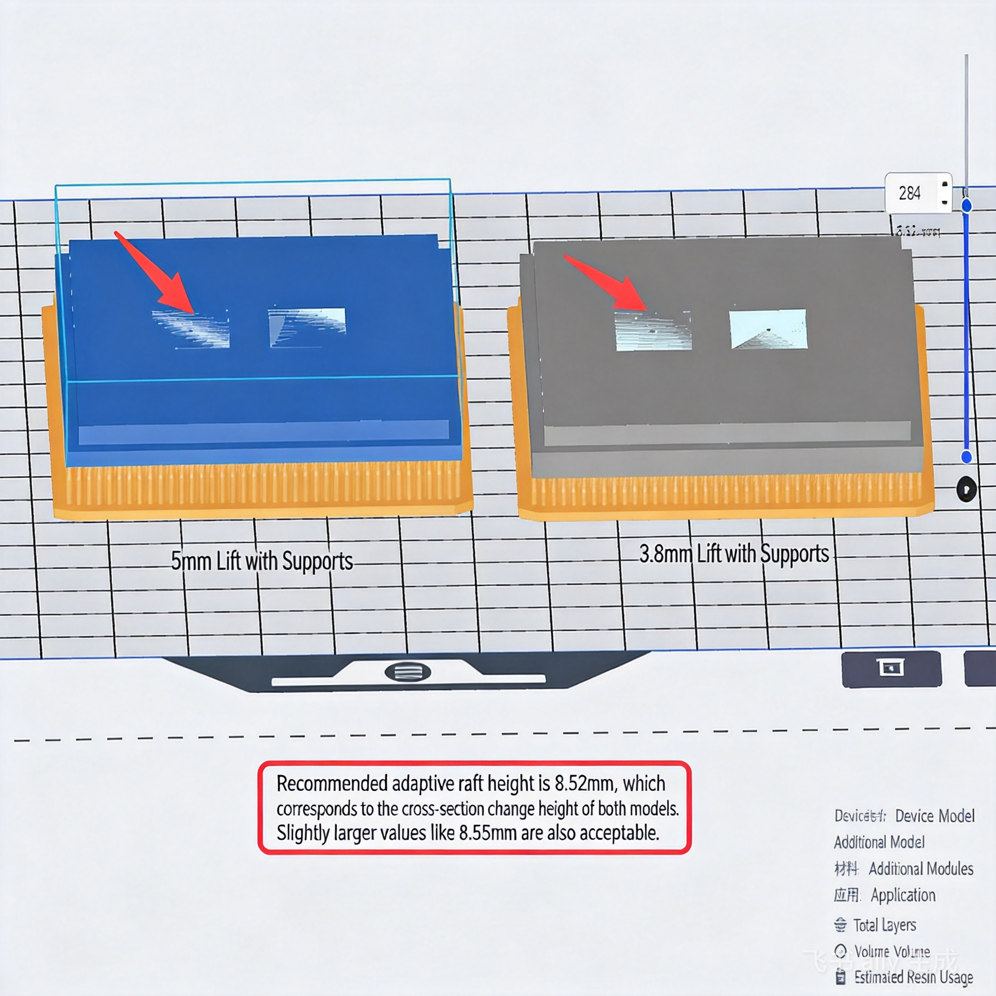
The raft height is a unified value. When a plate contains multiple cross-section mutation models and there are high requirements for the accuracy of the model's printing height, the height at the cross-section change of multiple models can be made basically consistent by adjusting the support elevation height.
 |
 |